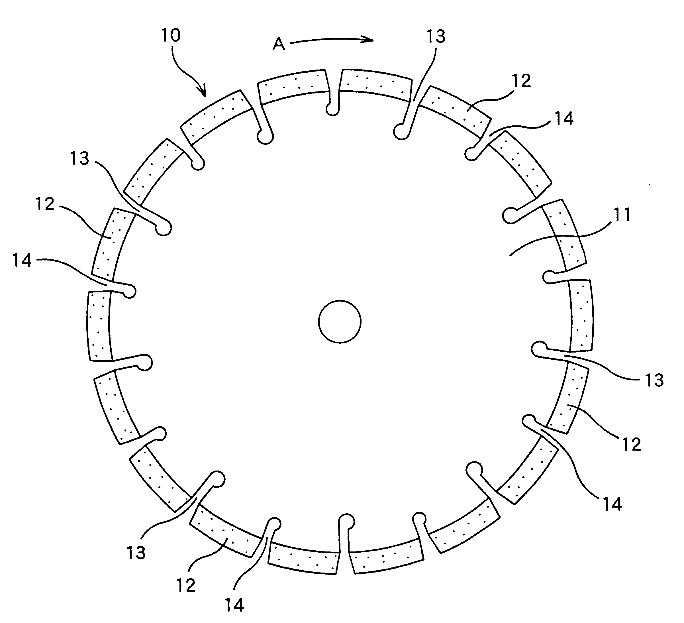
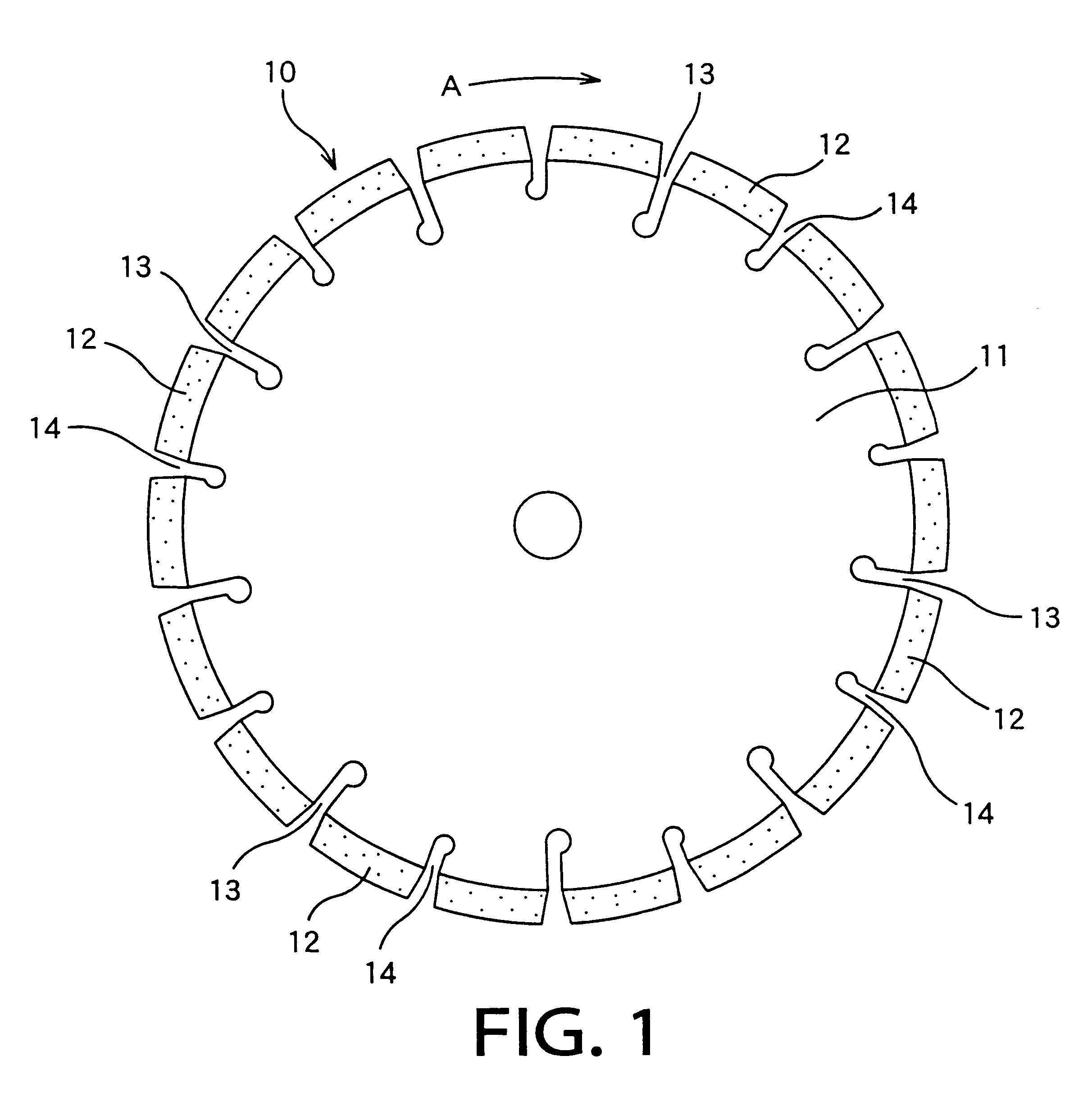
Various studies conducted by the present inventors under the above-described situation revealed that the wear of the neck portion of the cutting saw is reduced by suitably designing the shape of each slit formed in the outer circumferential surface of the base disk of the cutting saw. For example, the inventors found a fact that the wear of the neck portion is advantageously reduced where the opposed side surfaces of the slit are connected at their respective radially inner end portions to the part-cylindrical surface which has an inside
diameter larger than a circumferential distance between the radially inner end portions of the opposed side surfaces, such that one of the side surfaces is smoothly connected to the part-cylindrical surface without a stepped or protruding portion therebetween.
The above-described fact found by the present inventors is explainable by assuming that a small number of comparatively large eddy flows (e.g., a single flow) of the cutting chips are formed, in place of the turbulent flows, within each slit where the part-cylindrical surface is smoothly connected to one of the side surfaces without a stepped or protruding portion, and that the time for which the cutting chips stay in the slit is generally increased owing to the large eddy flow. That is, the large eddy flow tend to advantageously impede movements of the cutting chips out of each slit, or facilitate movements of the cutting chips into each slit, so that the ratio of ones of the produced cutting chips, which are caught in each slit and then carried by each slit out of the currently formed groove, to the entirety of the produced cutting chips is increased. Thus, an increased amount of the cutting chips are discharged from the groove after the slit comes out of the groove, thereby minimizing an amount of the cutting chips forced to be displaced into a small gap between the base disk and each side surface of the currently formed groove, and accordingly resulting in a reduced amount of wear of the base disk.
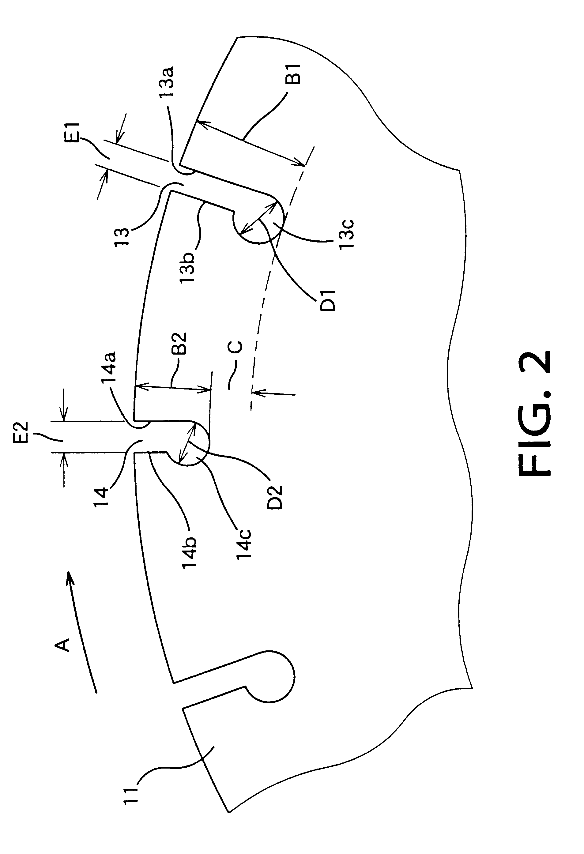
In the rotary cutting saw of the present invention, the opposed side surfaces of each slit are connected at their respective radially inner end portions to the part-cylindrical surface that has the circumferential width larger than the circumferential distance between the radially inner end portions of the side surfaces, and the part-cylindrical surface is smoothly connected to one of the side surfaces without a stepped portion therebetween. According to this arrangement, there is formed a single or small number of large eddy flow within each slit during a cutting operation. The large eddy flow advantageously impedes movements of the cutting chips out of each slit, or facilitates movements of the cutting chips into each slit, so that an increased amount of the cutting chips are caught in each slit and then carried by each slit out of the currently formed groove so as to be discharged from the groove after the slit comes out of the groove, thereby resulting in a reduced amount of wear in the neck portion of the base disk. This
advantage can be obtained, for example, even without bonding a wear-resistant
chip to one of the side surfaces of the slit. Therefore, the rotary cutting saw of the present invention does not suffer from a reduced efficiency of
discharge of the cutting chips from the currently formed groove or a reduced efficiency of application of the
cutting fluid to the cutting point, which would be caused by the presence of the wear-resistant chip, and which would reduce the cutting performance and the durability of the cutting saw. It is noted that the cylinder partially defined by the part-cylindrical surface of each of the slits may have a circular shape or an elliptical shape in a cross section perpendicular to the axial direction of the base disk.
According to a second preferred form of the invention, the side surfaces of each of the slits are parallel to the radial direction, and wherein the axis of the above-described cylinder is offset, in the circumferential direction by a predetermined amount, from a center plane between the side surfaces. The axis of the cylinder of each of the slits may lie on an extension of the other of the side surfaces which is other than the above-described one of the side surfaces, so that the circumferential width of the part-cylindrical surface is made about twice as large as the circumferential distance between the side surfaces, thereby further facilitating generation of a large eddy flow of the cutting chips within each slit.
According to a third preferred form of the invention, the above-described one of the side surfaces of each of the slits is located on the forward side of the other of the side surfaces as viewed in a rotating direction of the base disk. This arrangement permits easy formation of the large eddy flow of the cutting chips, since the cutting chips tend to be displaced, from a cutting point in which the work material is
cut by the abrasive segment, inwardly in the radial direction of the base disk and forwardly in the rotating direction of the base disk.

