

Gear shaping method and device and spiral bevel gear cutter
a technology of gear cutter and gear shaping method, which is applied in the direction of gear teeth, gear-teeth manufacturing apparatus, natural mineral layered products, etc., can solve the problems of heat crack development, limit in the reduction of machining time, and obstacle to the reduction of machining cos
- Summary
- Abstract
- Description
- Claims
- Application Information
AI Technical Summary
Benefits of technology
Problems solved by technology
Method used
Image

Examples
second embodiment
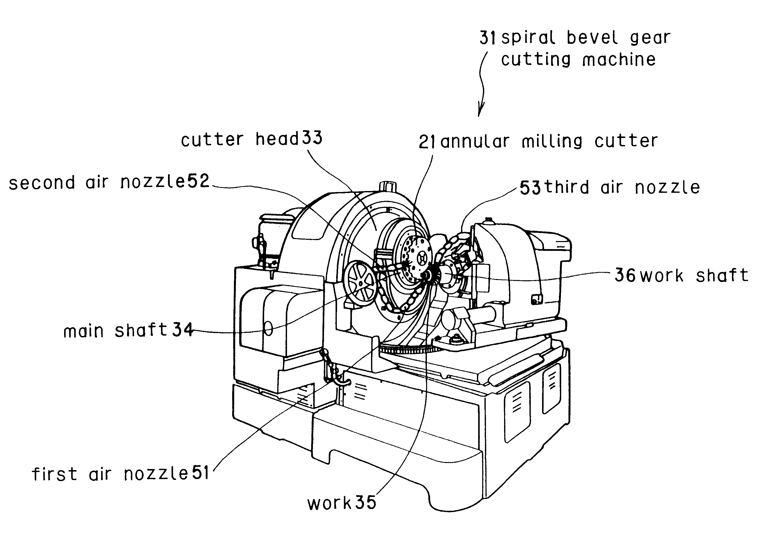
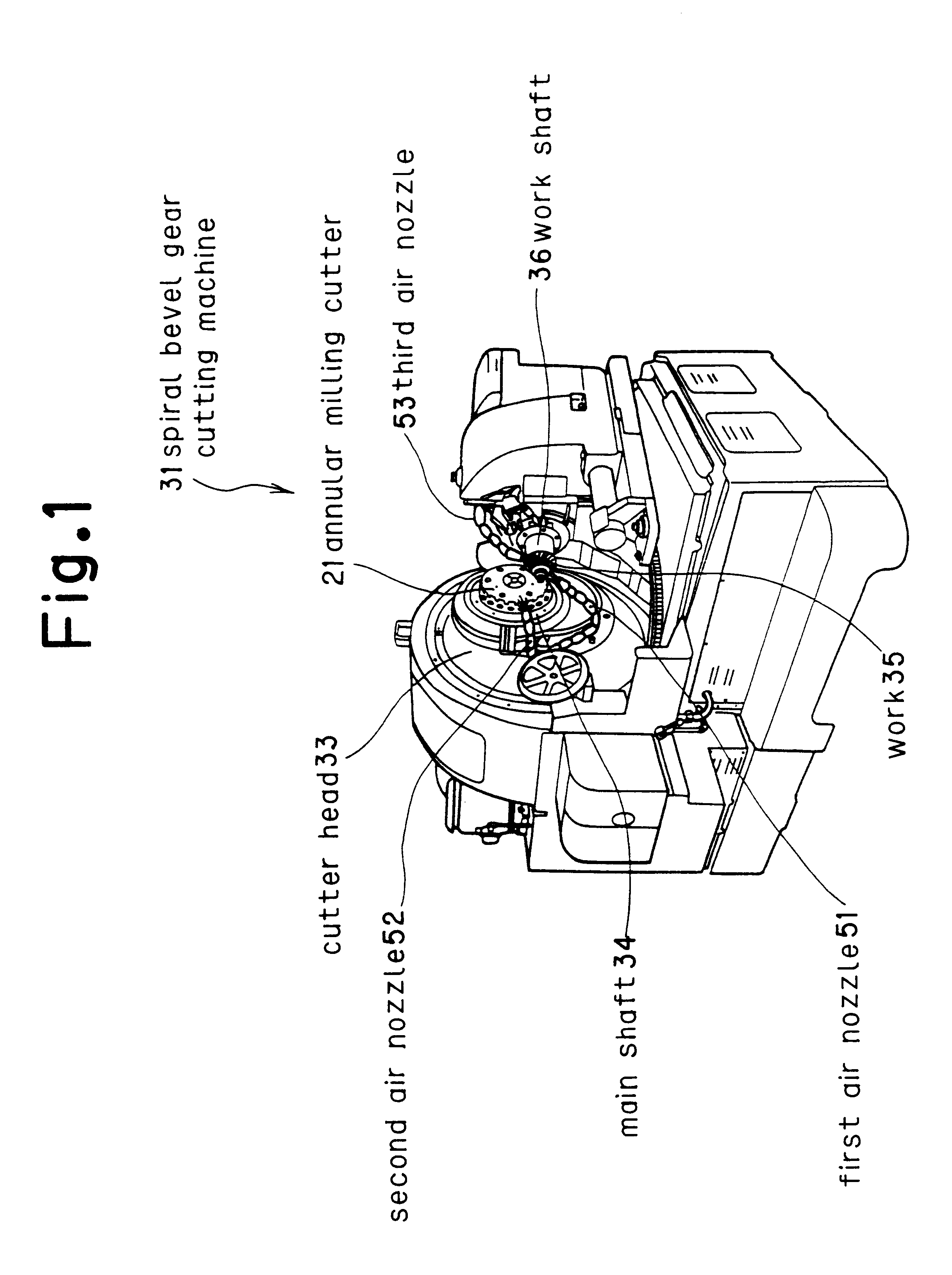
the gear cutting method of the present invention will be described. Using a blade material 23 made of a high-speed steel (SKH55) coated with one layer of 1.7 .mu.m thick film of a composition comprising (Ti.sub.0.5 Al.sub.0.5)(N.sub.y C.sub.(1-y)) as the blade material 23 of the annular milling cutter 21, cutting is performed without the supply of a cutting oil (dry cutting).
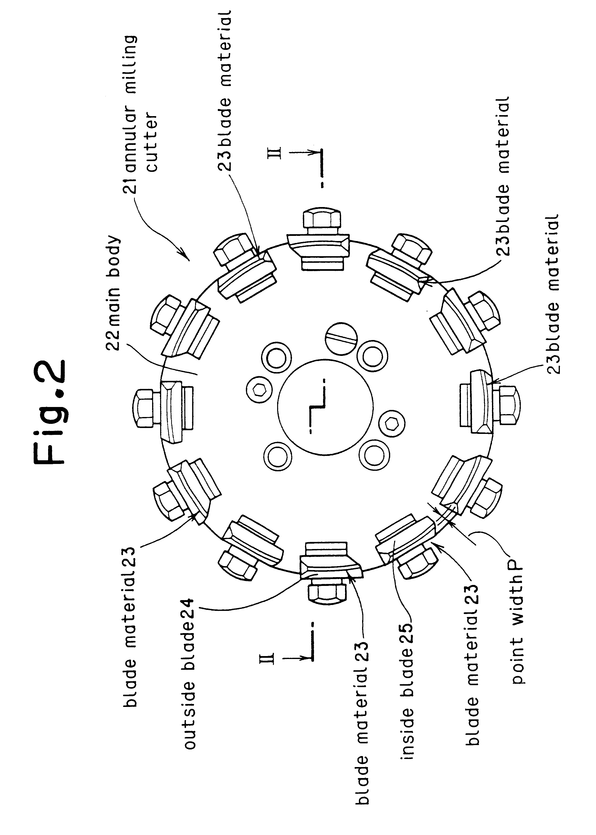
FIG. 6 shows the value of y of the material having the composition (Ti.sub.0.5 Al.sub.0.5)(N.sub.y C.sub.(1-y)) vs. flank wear, and FIG. 7 shows the value of y of the material having the composition comprising (Ti.sub.0.5 Al.sub.0.5)(N.sub.y C.sub.(1-y)) vs. crater wear. The blade material 23 in FIGS. 6 and 7 is a high-speed steel coated with one layer of a film of a composition comprising (Ti.sub.0.5 Al.sub.0.5)(N.sub.y C.sub.(1-y)), with a point width P of 0.06 inch, a pressure angle S of 10 to 20 degrees, and directed in the right direction, and the work is of a material of SCM435, the number of works to be m...
third embodiment
the gear cutting method of the present invention will be described. Using a blade material 23 made of a high-speed steel (SKH55) coated with a film of a thickness varied in the range of 0.5.ltoreq.d.ltoreq.1.7 .mu.m of a composition comprising (Ti.sub.0.5 Al.sub.0.5)N as the blade material 23 of the annular milling cutter 21, cutting is performed without the supply of a cutting oil (dry cutting). A film thickness d is when a single layer of (Ti.sub.0.5 Al.sub.0.5)N is used or a total thickness when a 0.05 .mu.m thick TiN is inserted in-between to form a multilayered film. Further, the blade material 23 has a point width P of 0.06 inch, a pressure angle S of 10 to 20 degrees, and is directed in the right direction. Still further, the main body 22 of the annular milling cutter 21 has a size of 6 inches, and the work is of a material of SCM435 and the number of works to be machined is 300.
FIG. 8 is a graph for determining an appropriate thickness of the coating of (Ti.sub.0.5 Al.sub.0....
fourth embodiment
the gear cutting method of the present invention will be described. Using a blade material 23 made of a high-speed steel (SKH55) coated with one layer of film of a composition comprising (Ti.sub.0.5 Al.sub.0.5)N as the blade material 23 of the annular milling cutter 21, cutting is performed while varying the axial feed without the supply of a cutting oil (dry cutting). The blade material 23 has a point width P of 0.06 inch, a pressure angle S of 10 to 20 degrees, and is directed in the right direction. Further, the main body 22 of the annular milling cutter 21 has a size of 6 inches, and the work is of a material of SCM435 and the number of works to be machined is 300.
FIG. 9 shows cutting speeds vs. axial feed falling under a practicable range of flank wear and crater wear. As shown in the figure, when the axial feed is 0.58 mm / bl, wear is in a practicable area up to a cutting speed of 360 m / min.
PUM
| Property | Measurement | Unit |
|---|---|---|
| cutting speed | aaaaa | aaaaa |
| cutting speed | aaaaa | aaaaa |
| pressure angle | aaaaa | aaaaa |
Abstract
Description
Claims
Application Information