
Active vibration isolating support device

a technology of active vibration and support device, which is applied in the direction of machine support, shock absorber, mechanical apparatus, etc., can solve the problems of reducing the durability of the actuator, increasing the power consumption of the coil, and deteriorating the characteristics of the magnetic circui

Inactive Publication Date: 2002-07-23
HONDA MOTOR CO LTD
View PDF9 Cites 66 Cited by
  • Summary
  • Abstract
  • Description
  • Claims
  • Application Information

AI Technical Summary

Benefits of technology

In addition, the other object of the invention is to provide an active vibration isolating support device which can ensure the detection of the abnormal state of the actuator.
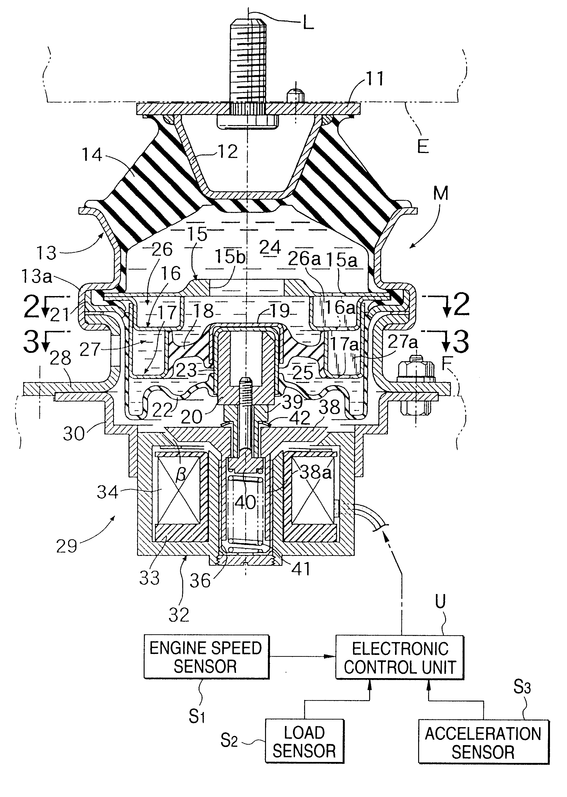
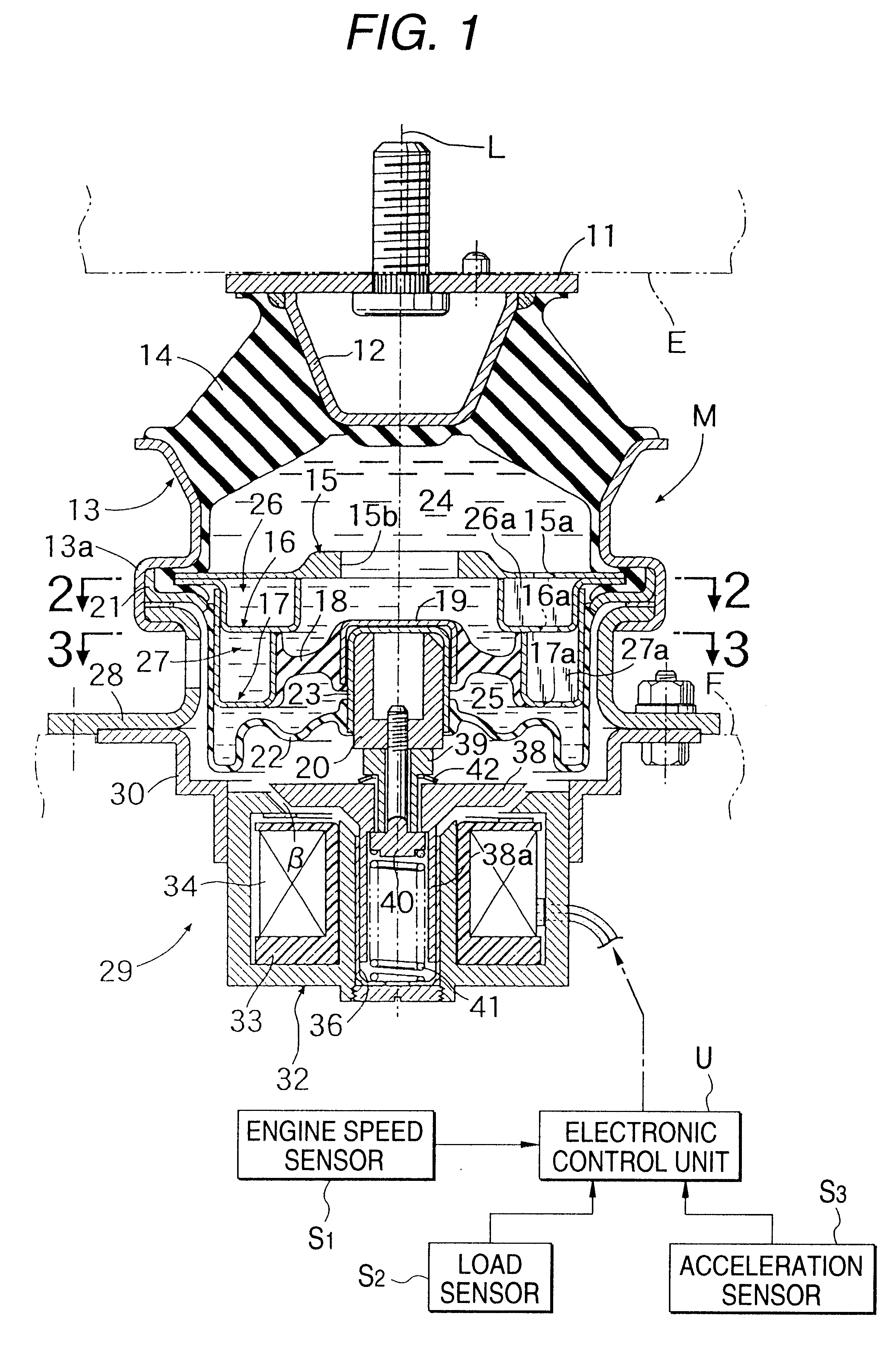
According to the above construction, since the armature of the actuator is supported by the bearing, the vibration of the armature can be prevented, whereby an optimum air gap can be set for the actuator, thereby making it possible to miniaturize the coil to thereby reduce the power consumption. Moreover, since the armature and the movable member are connected to each other in a flexible fashion, even if there occurs a vibration of the movable member due to the load imparted by the liquid chamber, the vibration is not directly transmitted to the armature, whereby biassed wearing of the bearing can be prevented, thereby making it possible to improve the durability and reliability of the actuator.
According to the above construction, since the armature of the actuator is supported by the bearing, the vibration of the armature can be prevented, whereby the optimum air gap can be set for the actuator and consequently, the coil can be miniaturized to thereby reduce the power consumption. Moreover, since the armature and the movable member are brought into contact with each other via the contact portion such that they can be displaced relative to each other, even if the vibration of the movable member is generated by the load imparted thereto by the liquid chamber, the vibration is constructed so as not to directly be transmitted to the armature, whereby the biassed wear of the bearing can be prevented, thereby making it possible to improve the durability and reliability of the actuator. Furthermore, since the armature press drives the movable member via the contact portion, the deviation of the armature from the movable member can be prevented, whereby the movable member can securely be driven.

Problems solved by technology

Thus, an air gap needs to be set so wide as to avoid a risk of the armature being brought into contact with a yoke even if it is inclined, this resulting in deterioration of the characteristics of the magnetic circuit.
To solve this problem, the magnetic force to be generated may be increased by enlarging the coil, but such a construction leads to increase in power consumption of the coil.
To cope with this, it is then considered to avoid a contact between the inclined armature and the yoke by supporting the armature by a bearing such that the armature moves along the axis of the device, but such a construction generates pinching between the armature and the bearing due to a biassed load imparted by the movable member, and it leads to a problem that the bearing wears too early, whereby the durability of the actuator is reduced.
In addition, since the conventional active vibration isolating support device is provided with no means for verifying the operational amount of the armature, even if the actuator fails and becomes out of order or the actuator gets deteriorated and the operational amount thereof is reduced, there is no way of detecting such an abnormal state, and this may result in a problem that the active vibration isolating support device cannot perform as originally designed.
Furthermore, since the operational amount of the actuator cannot be detected, the operation of the actuator cannot be feedback controlled, and this results in a problem that control with high accuracy is made difficult.

Method used


Image

  • Active vibration isolating support device
  • Active vibration isolating support device
  • Active vibration isolating support device

Examples


second embodiment

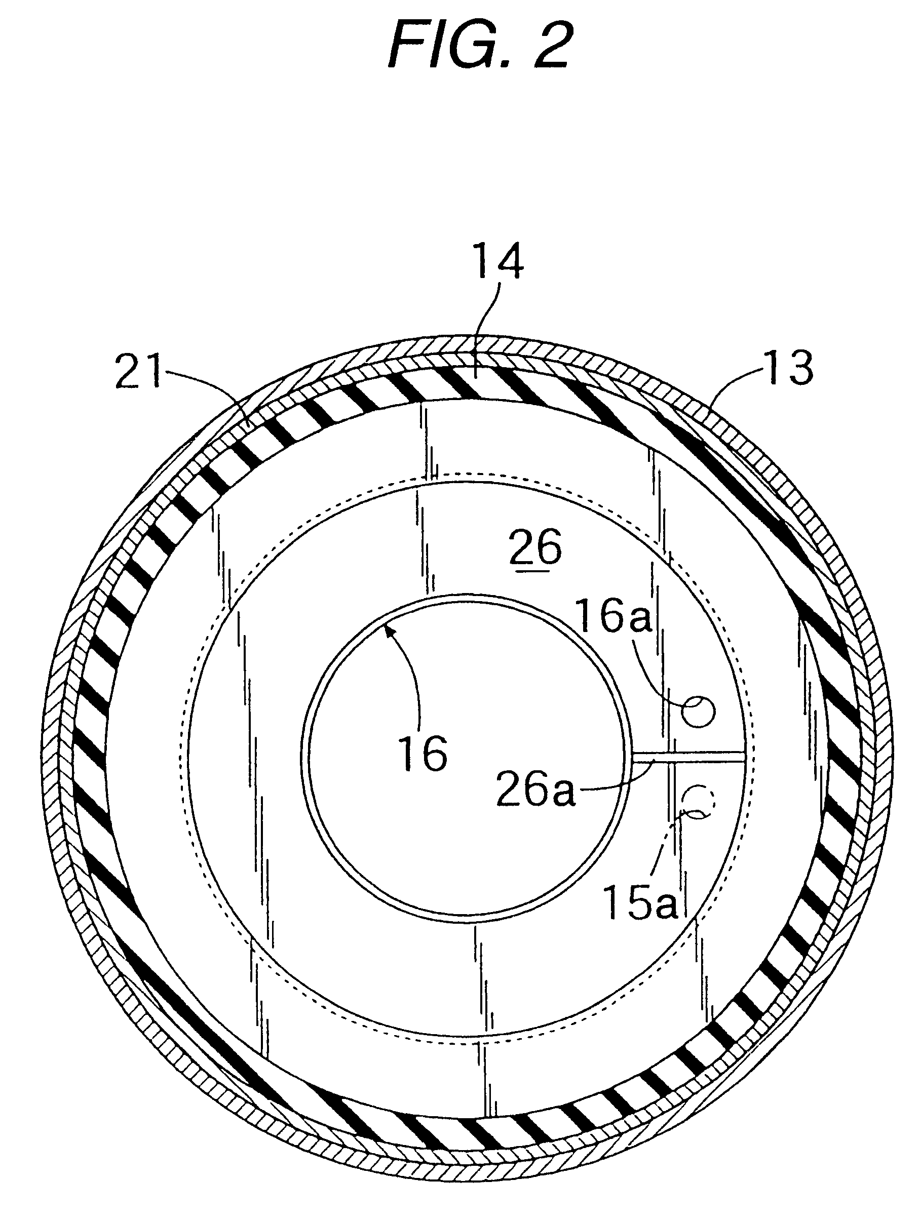
FIGS. 5 to 7 show a second mode for carrying out the invention or the invention, in which FIG. 5 is a vertical sectional view of an active vibration isolating support device, FIG. 6 is a cross-sectional view taken along the line 4--4 of FIG. 5, and FIG. 7 is an enlarged view showing a main part of FIG. 5. A cross-sectional view taken along the line 2--2 of FIG. 5 is identical to the cross-sectional view shown in FIG. 1 which is discussed with respect to the first mode for carrying out the invention.

first embodiment

The second embodiment is identical to the invention in the basic construction, and therefore, only different features will be described below. A second elastic body 18 formed of a rubber film is fixed at the outer circumference thereof through vulcanization bonding to the inner circumference of a third orifice forming member 17, and a second elastic body 18 is also fixed at the inner circumference thereof through vulcanization bonding to a movable member 20 disposed vertically movably on an axis L. A diaphragm 22 is fixed at the outer circumference thereof through vulcanization bonding to a ring member 21 fixed to a caulk fixed portion 13a of an outer barrel 13, and the diaphragm 22 is also fixed at the inner circumference thereof through vulcanization bonding to the movable member 20.

A yoke 32 is fixed to a actuator supporting member 30 and a coil 34 wound around a bobbin 33 is accommodated in the space formed in the interior of the yoke 32. A cylindrical bearing 36 is fitted in a ...


PUM


Abstract

An active vibration isolating support device for preventing the direct transmission of vibrations from an engine to a vehicle body frame includes an electromagnetic actuator for driving a movable member in a reciprocating fashion to change the capacity of a first liquid chamber. A shaft portion of an armature driven by a coil is supported by a bearing so that it moves along an axis, whereby the size of an air gap can be maintained as small as possible, thereby making it possible to miniaturize the coil. In addition, a connecting rod for connecting the movable member with the armature is supported so as to sway relative to a coil spring and a saucer spring, whereby the vibration of the movable member is prevented from being transmitted to the shaft portion of the armature.

Description

1. Field of the InventionThe present invention relates to an active vibration isolating support device comprising an elastic body for bearing the load of a vibratory body, a liquid chamber at least partially constituted by said elastic body, a movable member for changing the capacity of the liquid chamber and an actuator for driving an armature connected to the movable member by virtue of an electromagnetic force produced by a coil.2. Description of the Related Art An active vibration isolating support device as described above is known in Japanese Patent Unexamined Publication No. Hei. 10-110771(JP-A-10-110771).In this active vibration isolating support device, the movable member for changing the capacity of the liquid chamber is constituted by a disc-like plate spring secured to a case around the periphery thereof, and the armature driven by the coil of the actuator does not have any specific bearing and is supported directly on a lower surface of the movable member at a central p...

Claims


Application Information

Patent Timeline
IPC IPC(8): F16F13/04F16F13/26
CPCF16F13/26
Inventor NEMOTO, HIROTOMIIINUMA, KENOGAWA, TSUTOMUMATSUOKA, HIDEKIMIKASA, TETSUOWATANABE, SATOSHI
Owner HONDA MOTOR CO LTD
Learn More