Device for measuring a fill level of a liquid in a container

a technology for liquid filling and containers, applied in the direction of instruments, machines/engines, using reradiation, etc., can solve the problems of complex calculation of fill level, very inaccurate device provided for use in the fuel tank of a motor vehicle,

Inactive Publication Date: 2002-08-06
CONTINENTAL AUTOMOTIVE GMBH
View PDF19 Cites 27 Cited by
  • Summary
  • Abstract
  • Description
  • Claims
  • Application Information

AI Technical Summary

Problems solved by technology

A disadvantage of the known device is that the echo time of the reflected ultrasonic waves depends very strongly on the composition of the liquid and on its temperature.
The device provided for use in the fuel tank of a motor vehicle, in particular, is very inaccurate because the temperature of the fuel varies over a large range such as, for

Method used


Image

  • Device for measuring a fill level of a liquid in a container
  • Device for measuring a fill level of a liquid in a container
  • Device for measuring a fill level of a liquid in a container

Examples


Embodiment Construction

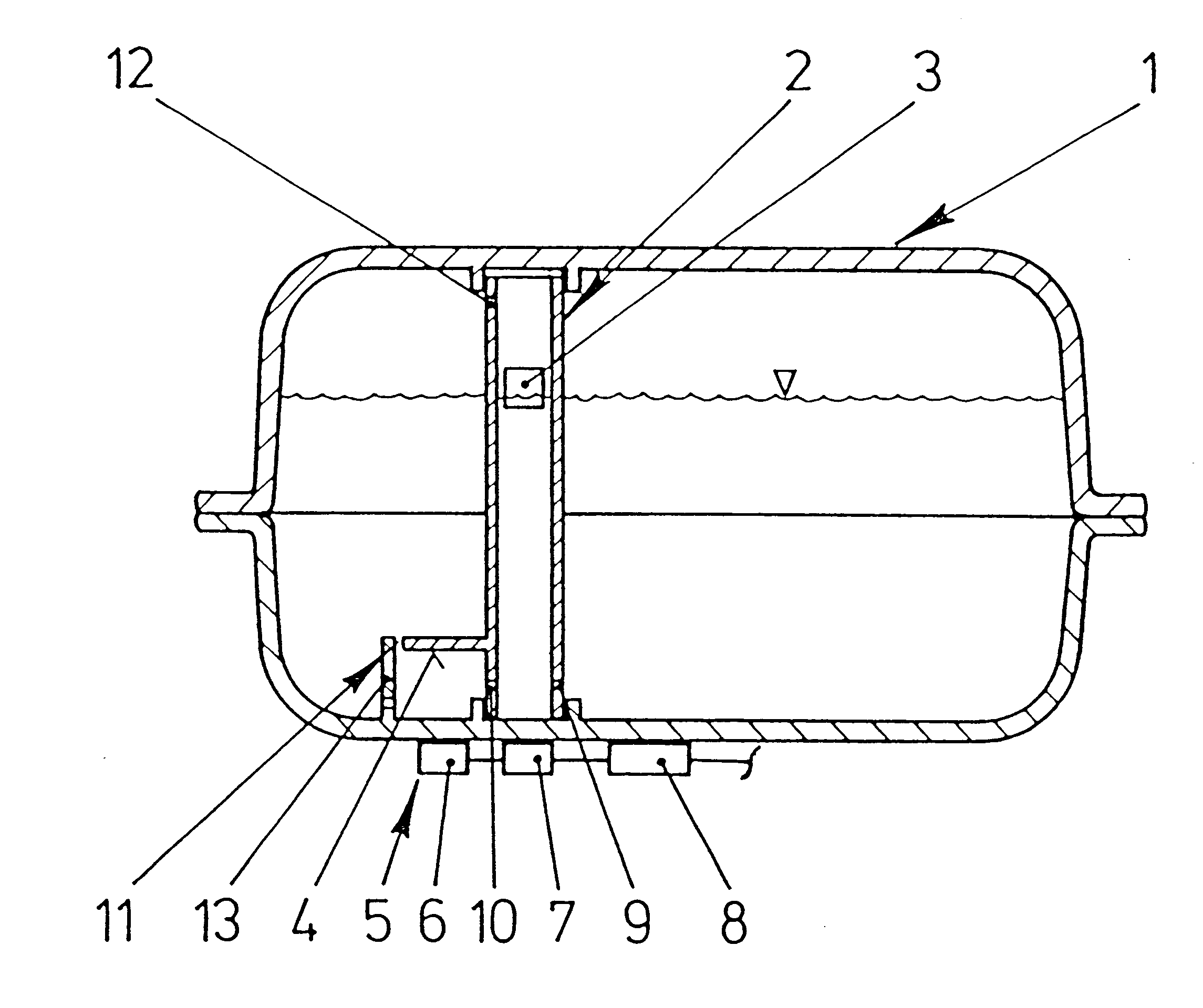
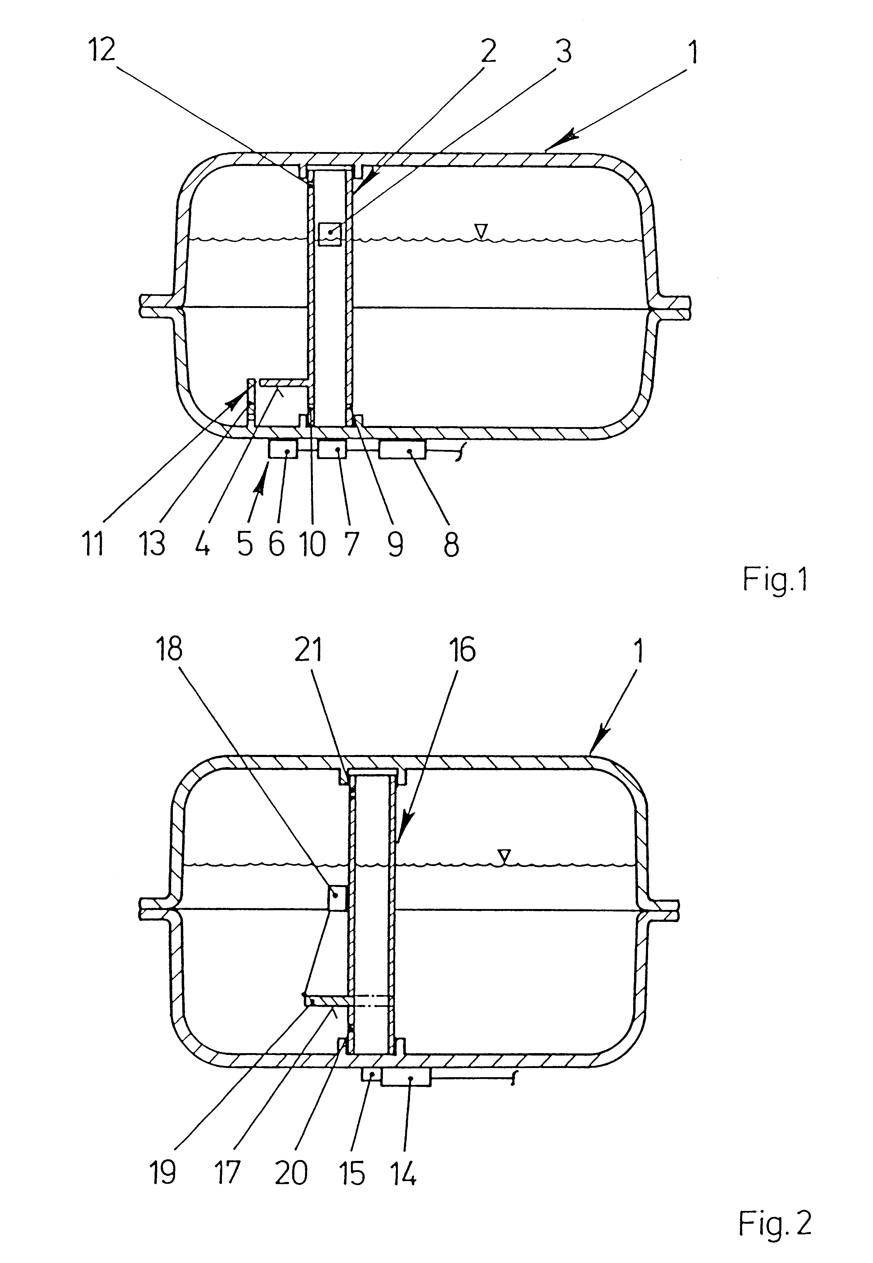
FIG. 1 shows a container 1 constructed as a fuel tank for a motor vehicle with a measuring tube 2 arranged therein. A float 3 is arranged in the measuring tube 2 so that the float 3 follows the liquid level in the measuring tube 2 and is guided by the sides of the measuring tube 2. A laterally projecting measuring reflector 4 is arranged on a side of the measuring tube 2. An ultrasonic sensor 5 with two sensor elements 6, 7 and an evaluation unit 8 are arranged on the outside of the tank 1. One of the sensor elements 7 is arranged below the measuring tube 2 while the other sensor element 6 is arranged below the measuring reflector 4. The sensor elements 6, 7 each transmit an ultrasound signal vertically upward and receive the reflection. The ultrasonic signal of the sensor element 7 is reflected by the float 3 and the ultrasound signal produced by the other sensor element 6 is reflected by the measuring reflector 4. The evaluation unit 8 measures the echo time, i.e., the time betwee...


PUM


Abstract

A device for measuring a fill level of a liquid includes an ultrasonic sensor with two sensor elements. One of the sensor elements determines the echo time of an ultrasonic wave to a float which follows the liquid level. The other of the sensor elements determines the echo time of the ultrasonic wave up to a measuring reflector arranged at a known distance from the other of the sensor elements. An evaluation unit compares the echo times and determines the fill level of the liquid from the ratio of echo times and from the known distance to the measuring reflector.

Description

1. Field of the InventionThe invention relates to a device for measuring a fill level of a liquid in a container, more specifically a fuel tank of a motor vehicle, the device having an ultrasonic sensor for generating ultrasonic waves in the liquid and for receiving the ultrasonic waves reflected in the region of the liquid level in the container and an evaluation unit for calculating the fill level of the liquid from the echo time of the ultrasonic waves received by the ultrasonic sensor.2. Description of the Related ArtA device for measuring the fill level of fuel in a fuel tank using an ultrasonic sensor is known in which the ultrasonic sensor has an outside diameter corresponding to the inside diameter of a measuring tube arranged in the fuel tank. The ultrasonic sensor is plugged into an end of the measuring tube. The measuring tube penetrates the bottom of the container and is filled with the liquid present in the fuel tank via compensating bores. To amplify the ultrasonic wav...

Claims


Application Information

Patent Timeline
IPC IPC(8): G01F23/296
CPCG01F23/2962G01F23/2968G01N2291/02836
Inventor KELLER, DIETER
Owner CONTINENTAL AUTOMOTIVE GMBH
Why Eureka
Try Eureka