Fuel-efficient tractor-trailer system

a tractor and trailer technology, applied in the direction of roofs, transportation and packaging, vehicle arrangements, etc., can solve the problems of trailer damage to the roof extension, the roof extension will not lift, etc., to improve the fuel mileage of the tractor used, improve the system operation, and reduce the effect of air resistan

Inactive Publication Date: 2002-08-06
GENERAL DYNAMICS C4 SYSTEMS
View PDF27 Cites 120 Cited by
  • Summary
  • Abstract
  • Description
  • Claims
  • Application Information

AI Technical Summary

Benefits of technology

A primary object and feature of the present invention is to provide a system for improving the fuel mileage of a tractor used in combination with a semi-trailer by improving the operation of the system controlling the panels that reduce air resistance in the area between the rear of the tractor and the front of the semi-trailer.
It is a further object and feature of the present invention to provide such a system with an improved rotation mechanism for the side panel extensions as they rotate against the side of the semi-trailer.
A further primary object and feature of the present invention is to provide such a system which is efficient, inexpensive, and handy.
According to yet another preferred embodiment of the present invention, there is provided a system for use with an over-the-road tractor of the type used to pull a semi-trailer, to assist turning operations and efficient air flow when substantially covering top and side gaps at a rear of the tractor (and in front of the semi-trailer), comprising, in combination: a tractor having a transmission with a reverse gear actuator and an air supply of compressed air; two side panels, each such side panel being respectively hingedly attached to such tractor to essentially cover each respective side gaps; at least one respective return spring attached to each respective side panel; and at least one rotator attached about every two vertical feet to each respective rear end of each respective such side panel wherein each such rotator is structured and arranged to assist a sliding of each such respective rear end of each such respective side panel along each respective side of the semi-trailer; wherein at least one such rotator comprises: a sprocket having five peripheral wheels, wherein such sprocket rotates around a first central axis and each respective such five peripheral wheels independently rotate around a respective second central axis, a roof extension comprising a rearward extension element at about the level of a roof of the cab; wherein such roof extension comprises a wear-plate structured and arranged to assist such roof extension to slide over a top of the semi-trailer when the semi-trailer is coupled to the tractor; and a roof extension support structured and arranged to support, in a normally substantially horizontal position such roof extension from a rear portion of the cab, and permit such roof extension to swivel upward and rearward, wherein such roof extension support comprises at least one hinge; and a pneumatically-powered piston system attached to such air supply, for supplying pneumatic pressure to such piston, of such tractor structured and arranged to extend at least one piston in such manner as to swivel such roof extension upward and rearward; and a switch system, attached solely to the tractor, structured and arranged to activate such pneumatically-powered piston system comprising, a switch structured and arranged, in a first position, to activate such pneumatically-actuated piston for supplying pneumatic pressure, wherein such switch is also structured and arranged, when in a second position, to de-activate such pneumatically-actuated piston for supplying pneumatic pressure, wherein such switch is structured and arranged to be operable by such reverse gear actuator, and wherein such switch is structured and arranged to be activated when such transmission is placed into a reverse gear and to be deactivated when such transmission is placed out of a reverse gear. It also provides such a system wherein such two side panels further comprise a rolled end portion structured and arranged to strengthen such two side panels and support such at least one rotator.

Problems solved by technology

A problem with this arrangement is that should, during the coupling maneuver, the tractor back up towards the trailer and not connect with the cam-arm, the roof extension will not lift and the trailer will damage the roof extension.

Method used


Image

  • Fuel-efficient tractor-trailer system
  • Fuel-efficient tractor-trailer system
  • Fuel-efficient tractor-trailer system

Examples


Embodiment Construction

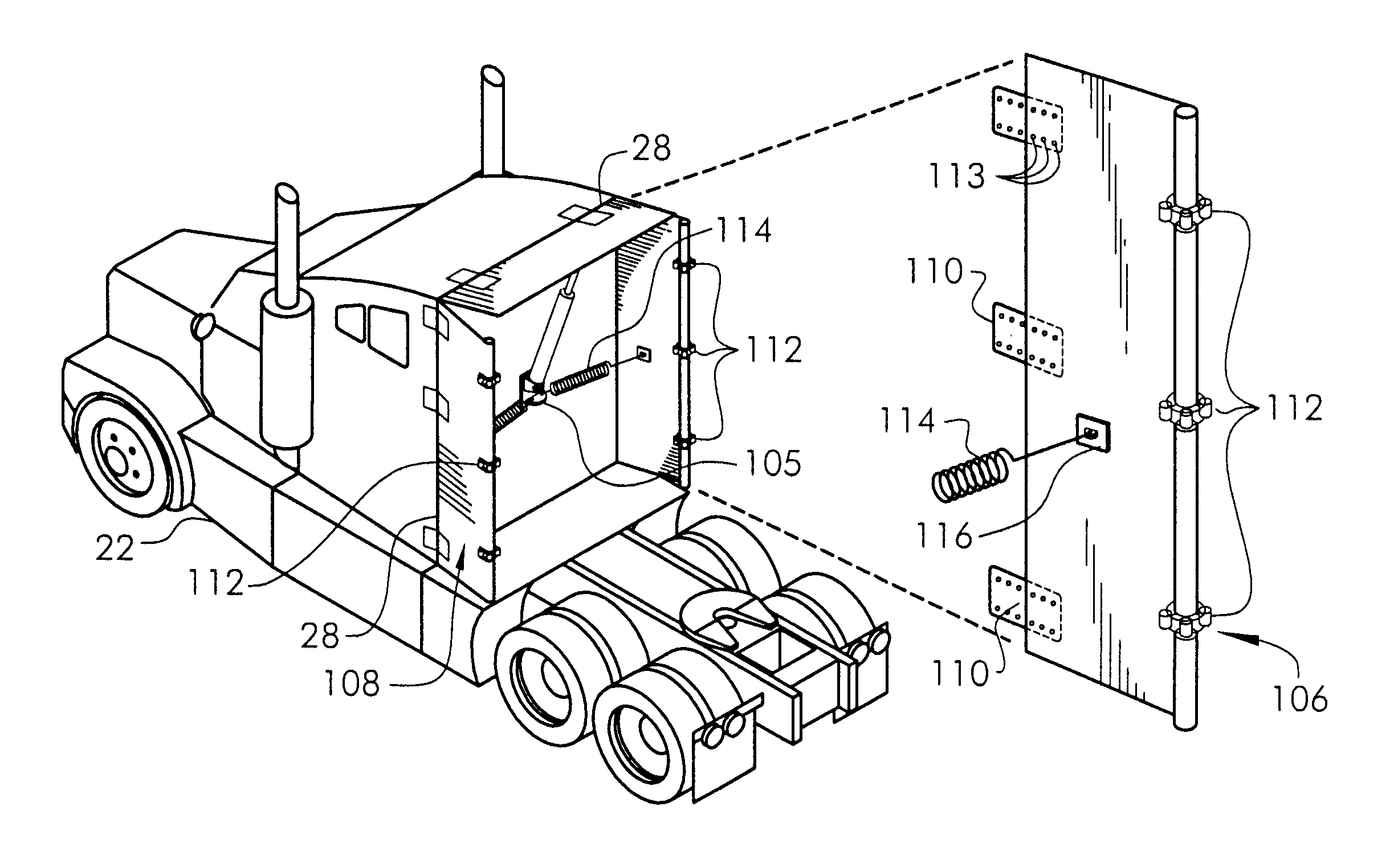
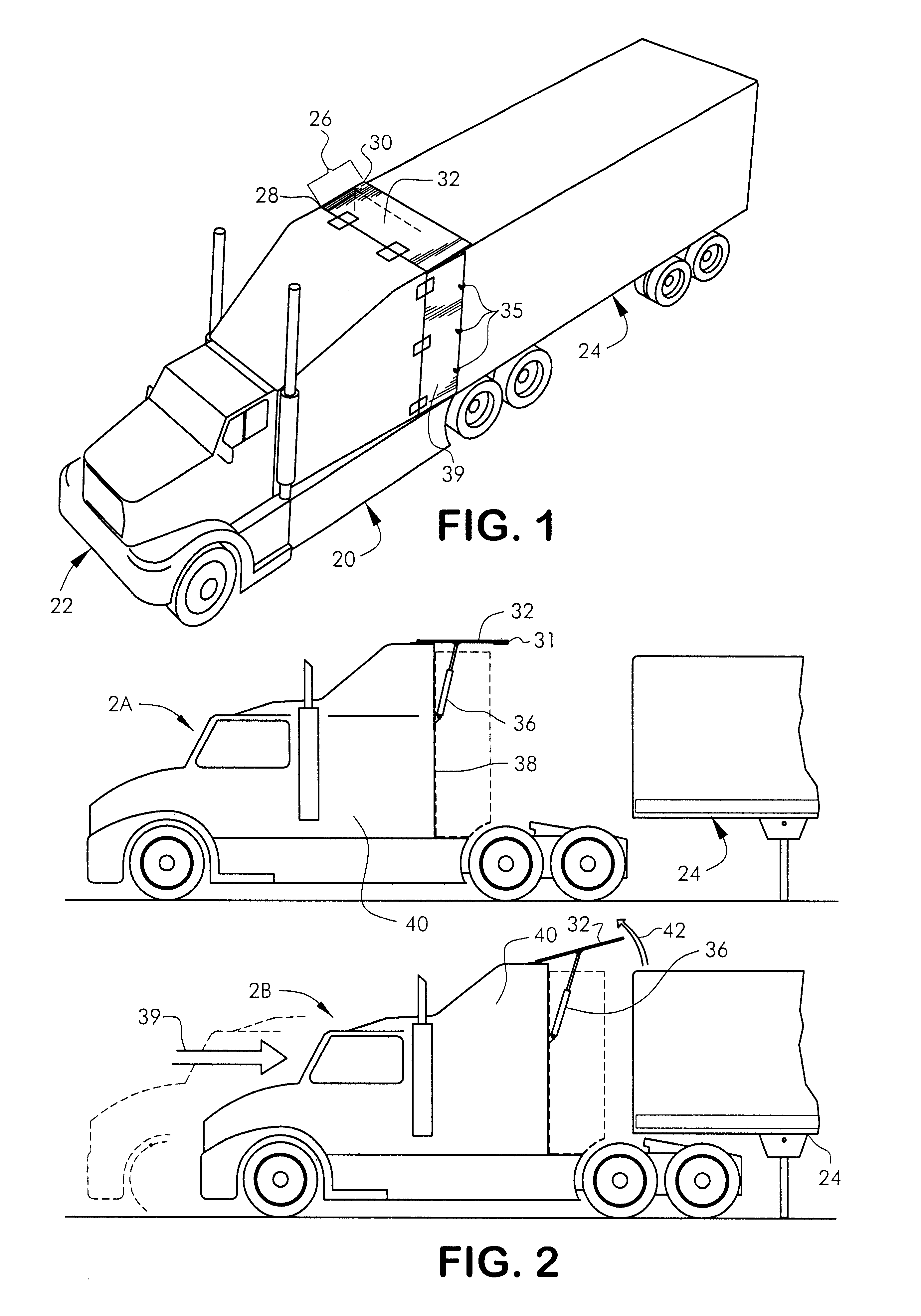
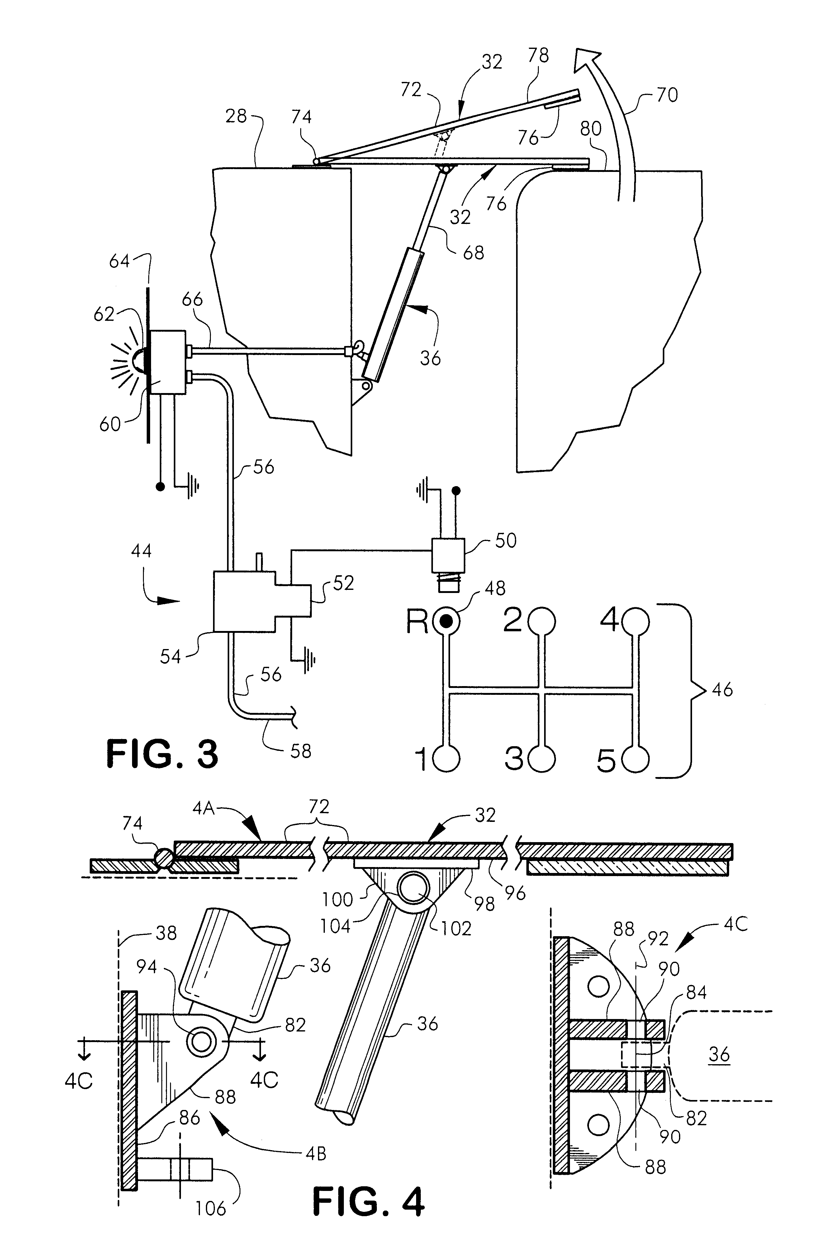
FIG. 1 is a perspective view of the fuel-efficient truck system 20 according to a preferred embodiment of the present invention. In a preferred embodiment, the fuel-efficient truck system 20 provides ways to improve a prior system for enhancing the fuel mileage of a tractor 22 and semi-trailer 24 combination, by improving the air flow and reducing the air resistance, that occurs in the spaces 26 (top gap and side gaps) between the rear 28 of the tractor 22 and the front 30 of the semi-trailer 24. In addition, a preferred embodiment of the invention provides an improved roof (the portion covering the top gap) lifting system, which automatically raises the roof extension portion 32 (embodying herein a roof extension structured and arranged to provide a rearward extension element at about the level of a roof of the cab) when the tractor 22 is put into reverse gear. Additionally, a preferred embodiment of the invention provides for a new rotating wheel 35 assembly (embodying herein at l...


PUM


Abstract

A fuel-efficient tractor-trailer system for improving the fuel mileage of a tractor-trailer combination by improving the air resistance that occurs in the area between the rear of the tractor and the front of the semi-trailer. The fuel-efficient tractor-trailer system provides an improved roof extension, which automatically raises when the tractor is put into reverse gear and an improved wheel mechanism for assisting the side extensions to slide around the semi-trailer ends when the tractor-trailer is turning. The fuel-efficient tractor-trailer system requires only modification to the tractor and not the trailer.

Description

This invention relates to providing a system for improving the fuel mileage of a truck tractor (of the type typically used in combination with a semi-trailer, hereinafter simply referred to as a tractor), and semi-trailer combination by improving the air resistance that occurs in the area between the rear of the tractor and the front of the semi-trailer. The present invention improves the prior art by providing an improved roof panel extension system, which automatically raises the roof panel adjoining the tractor and the semi-trailer when the tractor is put into reverse gear. In addition, there is provided an improved wheel mechanism for the side panel extensions.Typically, improvements to the airflow between the tractor cab portion and the semi-trailer portion relate to rigid or flexible extensions which are arranged to close the gap between the tractor cab portion and the semi-trailer portion. U.S. Pat. No. 5,078,448 discloses a device which provides a two-piece cab roof extender...

Claims


Application Information

Patent Timeline
Patent Type & Authority Patents(United States)
IPC IPC(8): B62D53/00B62D35/00B62D53/06B62D53/04
CPCB62D35/001B62D53/04B62D53/06
Inventor LISS, RICHARD M.
Owner GENERAL DYNAMICS C4 SYSTEMS
Why Eureka
Try Eureka