Transmission

a transmission and automatic technology, applied in the direction of gearboxes, gearing control, friction gearings, etc., can solve the problems of large fluid requirements and conflict between design objectives, and achieve the effects of avoiding or avoiding or avoiding friction, facilitating the grinding of sealing surfaces, and good alignment of piston faces

Inactive Publication Date: 2002-08-06
SCHAEFFLER TECH AG & CO KG
View PDF12 Cites 26 Cited by
  • Summary
  • Abstract
  • Description
  • Claims
  • Application Information

AI Technical Summary

Benefits of technology

A preferred embodiment of the invention has a charging circuit that leads from the flow-back circuit to the intake portion of the pump. Thus, the flow-back circuit, which carries the working medium coming from the high-pressure area as well as the run-off from the flow-regulating device, also supplies the intake portion of the fluid-conveyor pump in addition to the cooled and / or lubricated element(s), so that the intake portion can be charged, whereby the noise-generating properties of the fluid-conveyor device are improved.
In a preferred embodiment, the insert component has the shape of a ring that can be slid onto the piston. With this arrangement, it is especially preferred for the valve piston to have a larger diameter at the side facing the valve seat than at the side that faces away from the valve seat, with the diameter at the side facing away from the valve seat being smaller than the internal ring diameter of the insert component. This allows the insert component to be easily slid over the end of the piston that faces away from the valve seat for the installation of the insert component on the step or, more specifically, on the seat face. Thus, the insert component can be made as a closed ring that is merely put in place on the piston. Under a special concept for the manufacture of the piston with the insert component, the insert component is first put in place on the step, i.e., at the seat face of the valve piston and, subsequently, the finishing operations are performed on the insert component together with the seat face of the piston.

Problems solved by technology

This creates a conflict between design objectives in transmissions of the known state of the art.
This requires large quantities of fluid.
Consequently, this causes a conflict because the control of the transmission requires a smaller amount of fluid than the lubricating and cooling functions.

Method used


Image

  • Transmission
  • Transmission
  • Transmission

Examples


fourth embodiment

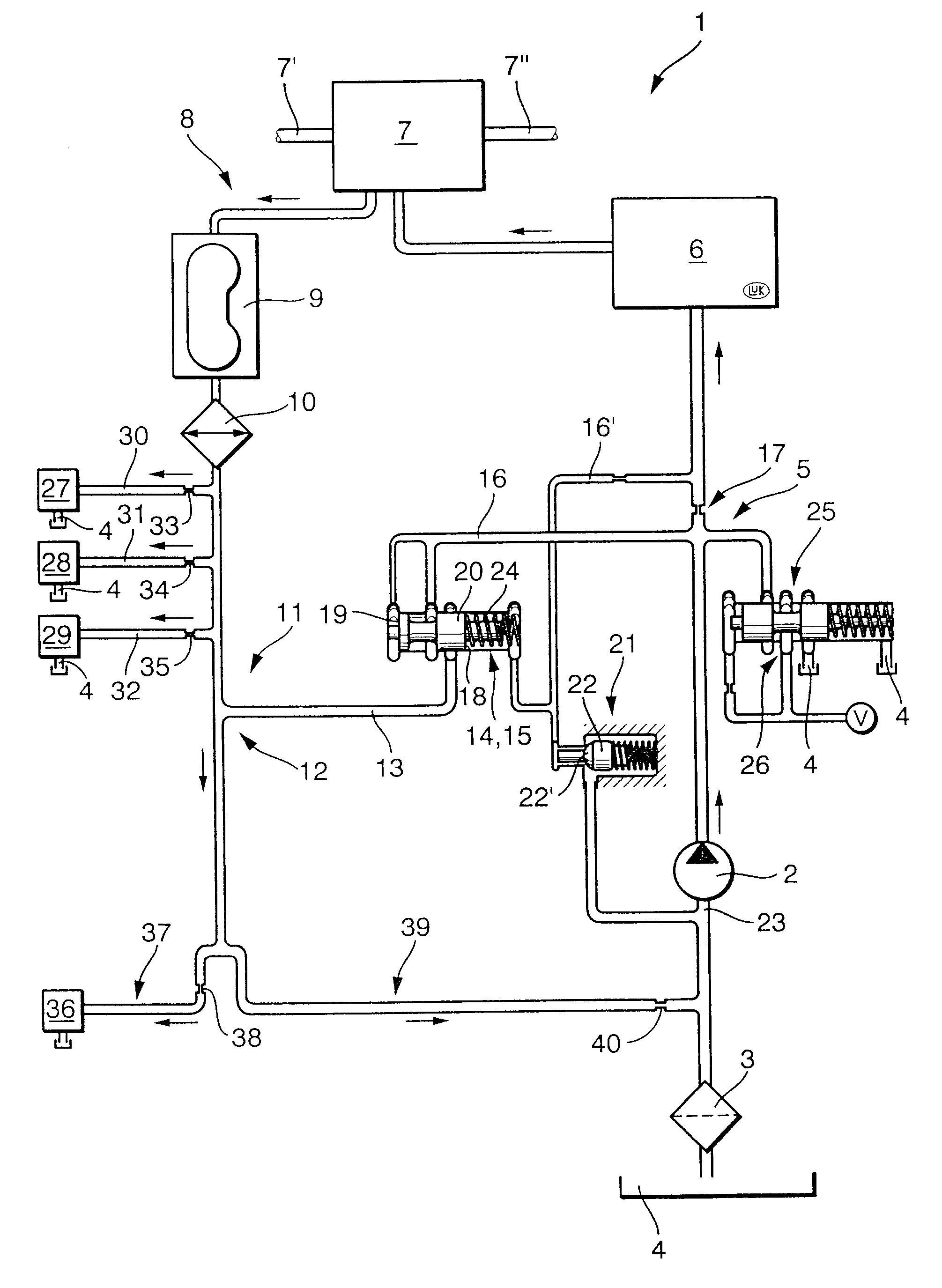
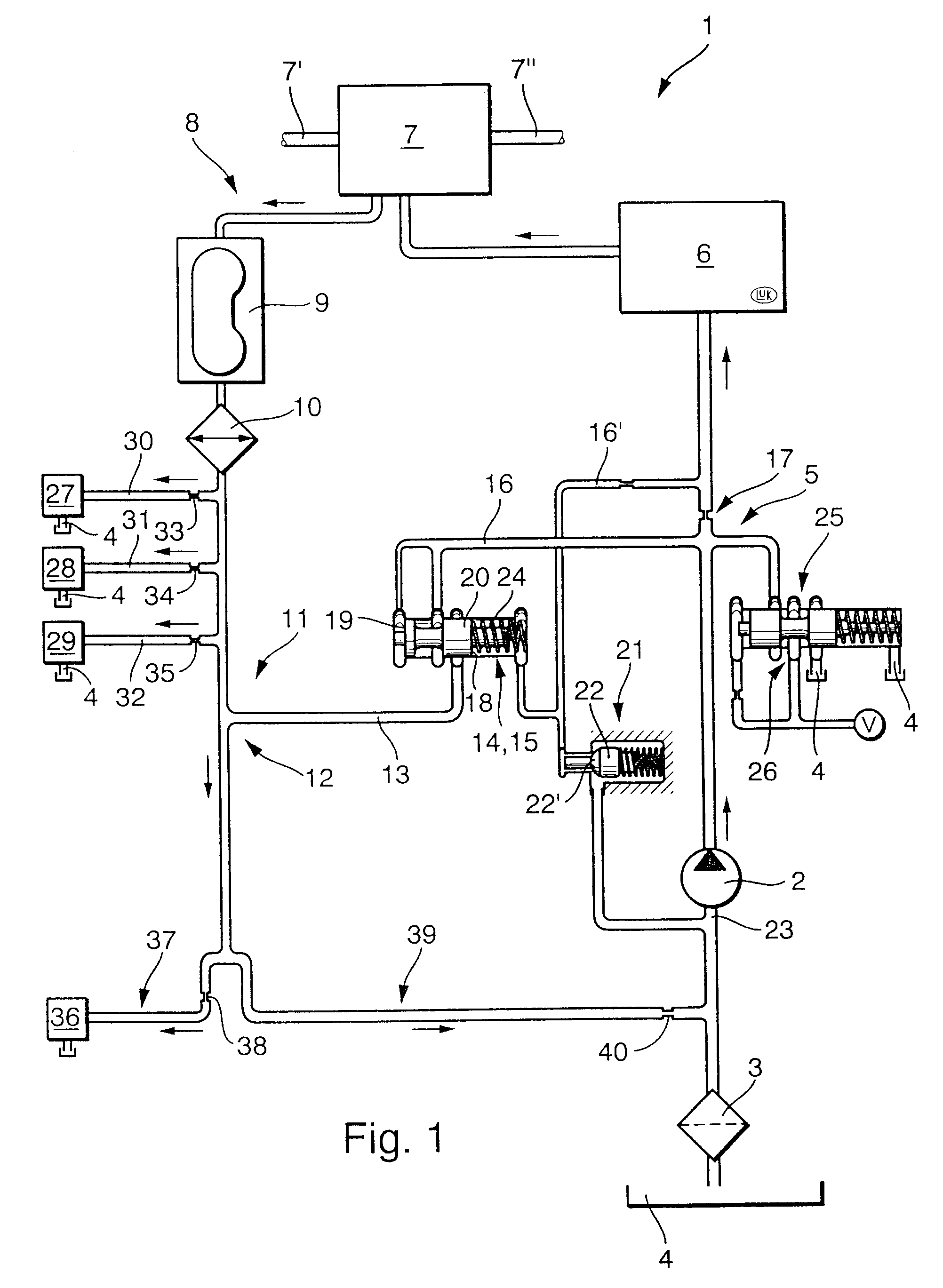
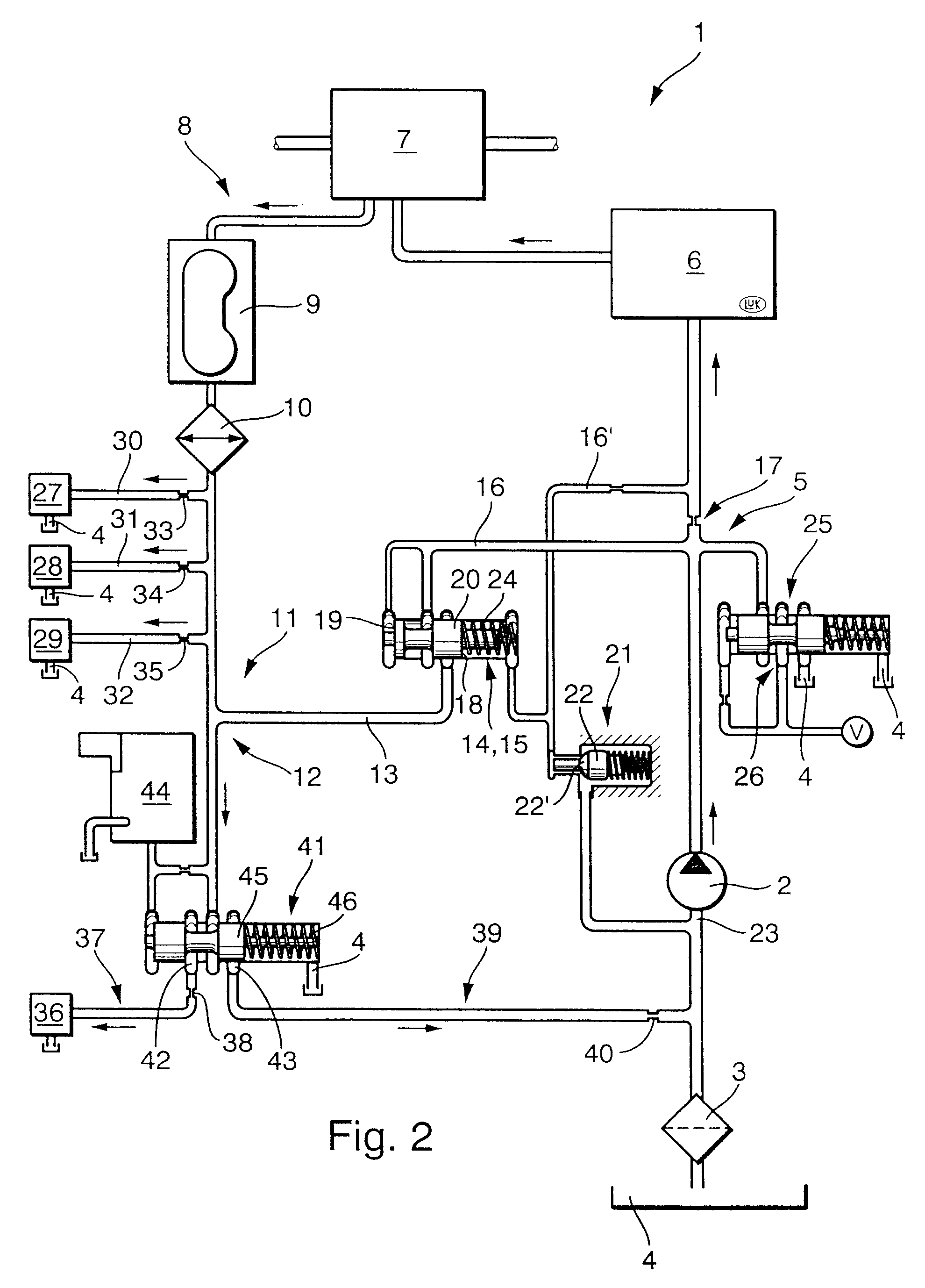
FIG. 4 illustrates an automatic transmission 1. The parts in FIG. 4 that are identical or have identical functions as in the preceding FIGS. 1 to 3 are again identified by the same reference symbols.

According to FIG. 4, the return circuit 8 leads from the transmission control system 6 to the converter 9. This configuration is based on the fact that the return circuit preferably follows after the last pressure-limiting valve in the high-pressure circuit. In FIGS. 1 to 3, the last pressure-limiting valve is a so-called torque sensor, which is used in cone-pulley belt-drive transmissions to set the contact pressure that the cone-pulley discs exert against the chain-belt. In the automatic transmissions of FIGS. 1 to 3, the torque sensor (not shown) acts as a pressure-limiting valve and, consequently, the return circuit follows the torque sensor. In the embodiment of FIG. 4, however, the last pressure-limiting valve is arranged in the transmission control system 6 and is configured, e.g....

first embodiment

FIG. 5 illustrates the threshold-pressure valve 50. The valve bore 53 is closed off by a plug 56 that is inserted in the valve bore 53 with a seal-ring element 57. The valve bore 53 is configured with steps and has three sections of different diameter, i.e., a first section with a diameter d1, a second section with a diameter d2, and a third section with a diameter d3. Furthermore, there are internal ring channels 58 and 59 inside the valve bore. Ring channel 58 communicates with the output port 43 of the switching device 41', and ring channel 59 communicates with the intake portion 23 of the fluid conveyor device 2. Adjoining the ring channel 59 in the section of diameter d2 is a valve seat 60 that is conically sloped in relation to the lengthwise central axis 61 of the valve bore 53. Thus, the valve seat is formed in a side wall of the ring channel 59. Coming from the bore section of 25 diameter d1, the valve seat 60 is located at the step or transition to the section of diameter ...


PUM


Abstract

A transmission has an rpm-converter controlled by a hydraulic system. The hydraulic system has a supply circuit from a fluid-conveyor device to the rpm-converter, a return circuit to carry the spent fluid back from the rpm-converter, and a run-off circuit to return the run-off portion of fluid from a flow-regulating device that regulates the volume flow in the supply circuit. The return circuit and the run-off circuit are merged in a circuit junction that continues into a flow-back circuit.

Description

The invention relates to a transmission, specifically an automatic, continuously variable transmission. Known transmissions of the kind discussed hereinafter have an rpm-converter means for converting an input rate of rotation (input rpm rate) to an output rpm rate, a transmission-control system for the rpm-converter means, as well as a supply circuit for the rpm-converter means into which a working fluid is fed by a fluid-conveyor device. The supply circuit carries the working fluid supplied by the pump by way of the transmission-control system to the rpm-converter means for setting different rpm-conversion ratios. A return circuit carries return fluid out of the rpm-converter means and / or the control system, e.g., to a reservoir tank for the working fluid. At least one branch conduit runs from the return circuit to provide at least one cooled and / or lubricated element of the transmission with working fluid. The transmission is further equipped with a flow-regulating device in the ...

Claims


Application Information

Patent Timeline
Patent Type & Authority Patents(United States)
IPC IPC(8): F16H57/04F16H61/00F16H61/66F16H57/02
CPCF16H57/0434F16H61/0021Y10T477/6237F16H2061/0037Y10T477/6243F16H61/66
Inventor FRIEDMANN, OSWALDAGNER, IVO
Owner SCHAEFFLER TECH AG & CO KG
Why Eureka
Try Eureka