Sensor and evaluation system, in particular for double sensors for determining positions and limit values

Inactive Publication Date: 2002-08-06
PEPPERL FUCHS GMBH
View PDF3 Cites 30 Cited by
  • Summary
  • Abstract
  • Description
  • Claims
  • Application Information

AI Technical Summary

Benefits of technology

The invention is based on the objective of creating a sensor and evaluation system of the type described above, in which the configuration of the individual sensors to form a system is simplified and the wiring effort between the sensors and the swi

Problems solved by technology

If an object to be measured is brought closer to the active surface of the sensor, then the current consumption of the sensor changes, for example, as a result of eddy-current losses in the object to be measured, and thus the current flow in the evaluation unit also changes.
This calls for quite complex wiring, which is disadvantageous for many applications.
However, when work is done with inherently safe control circuits corresponding to DIN 19234 NAMUR), this has the drawback that the resultant sum current has to be taken into account in the verification of the inherent safety since, with NAMUR which provides that each of two sensors is a two-wire direct current sensor that oper

Method used


Image

  • Sensor and evaluation system, in particular for double sensors for determining positions and limit values
  • Sensor and evaluation system, in particular for double sensors for determining positions and limit values
  • Sensor and evaluation system, in particular for double sensors for determining positions and limit values

Examples


Example

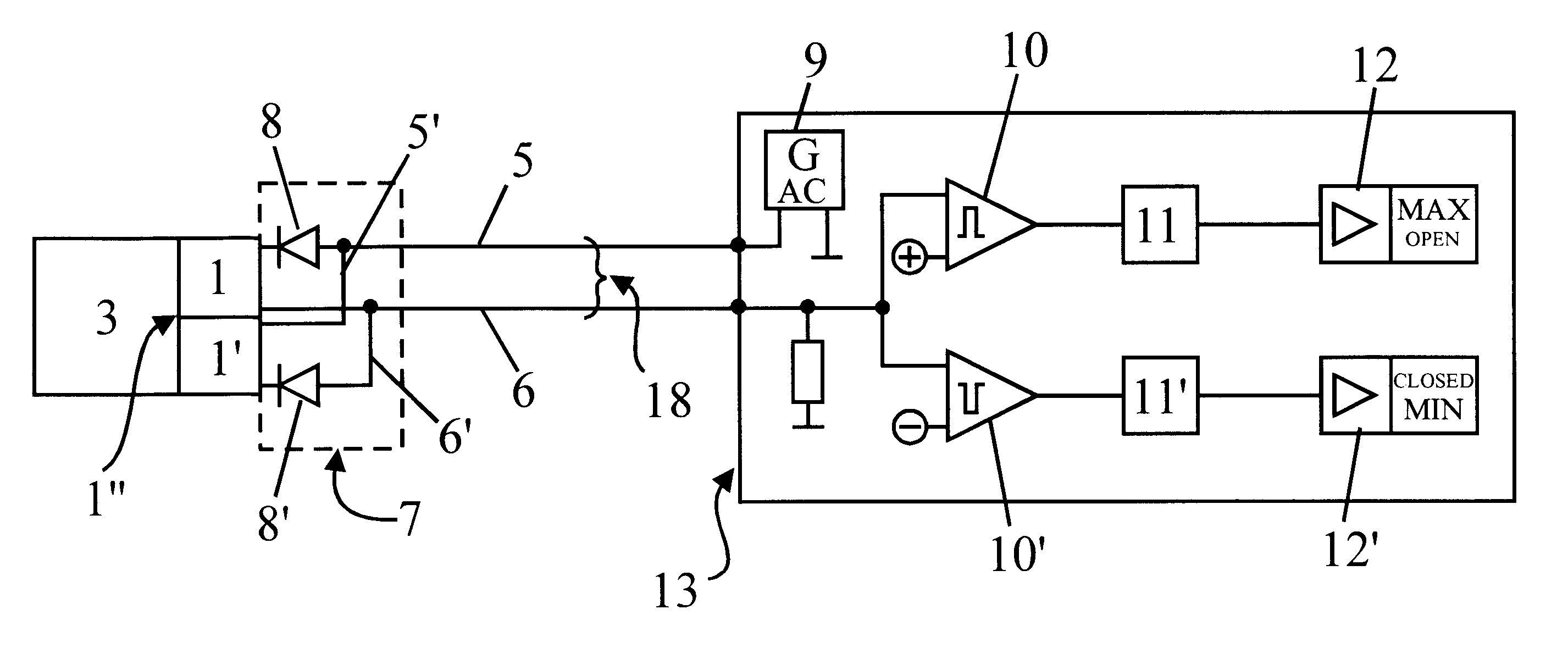
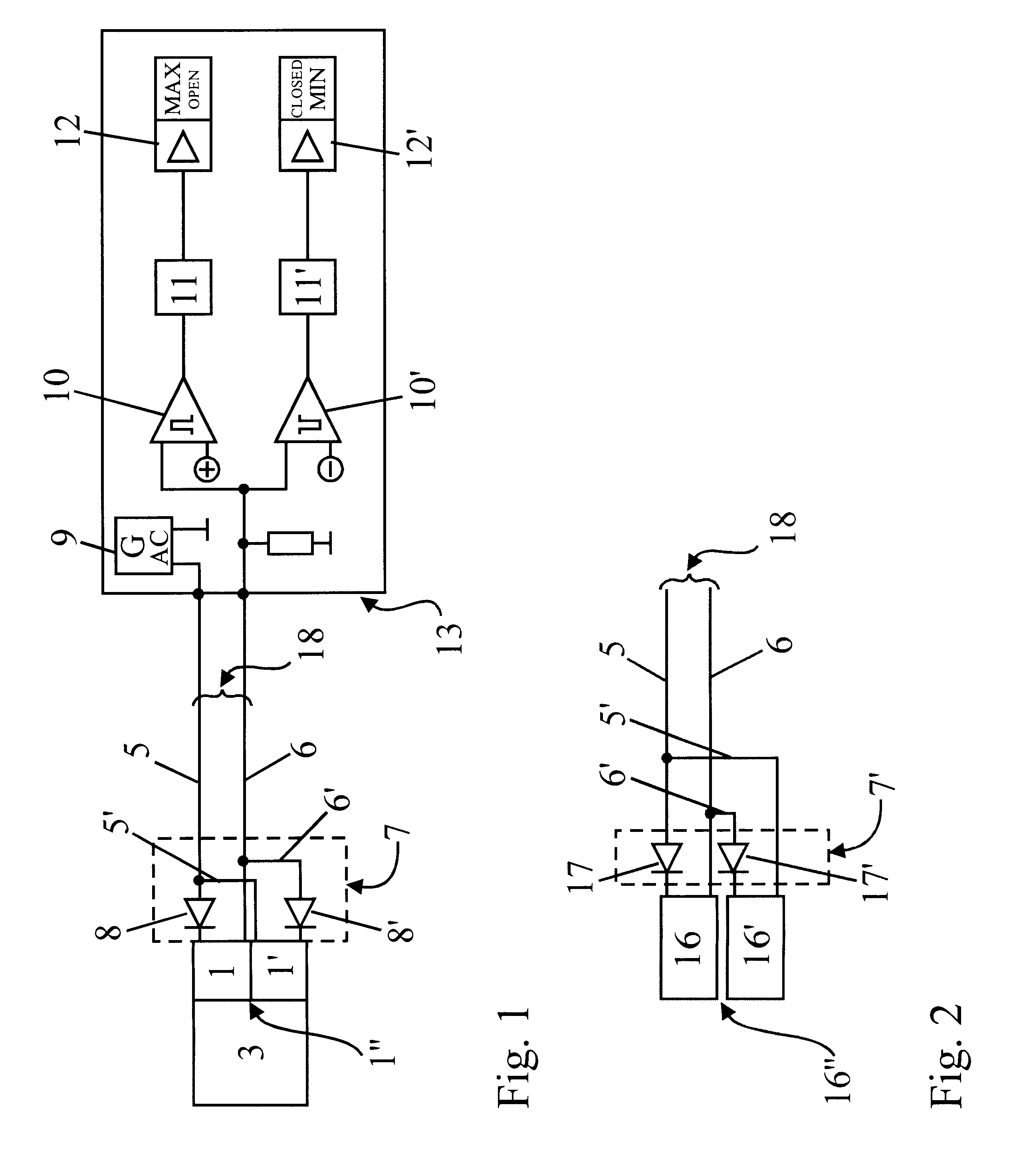
FIG. 1 shows a block diagram of a sensor and evaluation system with two sensors 1 and 1' coupled to form a sensor pair 1", or a double sensor 1". The sensors 1, 1' serve for purposes of measured value acquisition at a measuring point 3, e.g. for detecting two end positions of an object to be measured that define a tolerance range, or for detecting a pressure or a valve position. The sensor pair is connected by two connection wires 5, 6 to a switching amplifier 13, which contains a source of alternating current 9 for supplying current to the sensor pair 1" as well as evaluation units 10, 10' and storage units 11, 11' and output stages 12, 12' for the evaluation and output of the sensor signal or of the information about the state of the sensor. The switching amplifier is, for example, a buffer amplifier.

For the most part, the two connection wires 5 and 6 are associated with the sensors 1 and 1' of the sensor pair 1" and form a largely shared control circuit 18. The connection of the ...


PUM


Abstract

The invention relates to a sensor and evaluation system for capturing data at a measuring station (3), in particular for use in double sensors for determining end positions and limit values. The individual sensors (1, 1', 2, 2', 16, 16') are operated as sensor pairs (1'', 2'', 16'') by a largely shared control circuit consisting of two connecting lines (5, 6) with an electric current or voltage of alternate polarity. A state of a sensor (1, 1', 2, 2', 16, 16') is transmitted on the corresponding half-wave of the sensor current and evaluated by a switching amplifier (13) in relation to polarity and amplitude. Said sensor and evaluation system reduces the number of connecting lines required. In addition, interference from neighboring sensors is largely excluded, so that sensors can be mounted more closely together in a system. Said sensor and evaluation system is especially suited for equipment required to comply with the DIN 19234 (NAMUR) standard.

Description

TECHNICAL AREAThe invention relates to a sensor and evaluation system for acquiring data at a measuring point, especially for double sensors for detecting final positions and limit values, consisting of at least two sensors that are connected via a control circuit to a remotely located switching amplifier with a current source or voltage source, whereby a connection wire leads from the current source or voltage source to the sensor and another connection wire leads from the sensor to an evaluation unit, and the sensor signal of each sensor normally consists of a change in the current flow as compared to the current flow in the quiescent state of the sensor and said sensor signal is transmitted via the control circuit to the switching amplifier in order to be evaluated there in an evaluation unit and to be output at an output stage in the form of signals (e.g. binary ZERO, ONE) as a function of the sensor and of the time, according to the generic part of claim 1.STATE OF THE ARTSenso...

Claims


Application Information

Patent Timeline
IPC IPC(8): G01D5/243G01D5/12G08C19/30G08C15/00
CPCG01D5/243G08C19/30
Inventor BANSEMIR, WERNERJUNG, GERHARD
Owner PEPPERL FUCHS GMBH
Why Eureka
Try Eureka