Endoscope with objective lens drive mechanism

a technology of drive mechanism and endoscope, which is applied in the field of endoscope, can solve the problems of optical objective lens system, lens drive mechanism suffers from a drastic increase in the diameter of an assembly of the objective lens system, and is not easy to incorporate two independent drive means into the insertion instrumen

Inactive Publication Date: 2002-09-10
FUJI PHOTO OPTICAL CO LTD
View PDF7 Cites 33 Cited by
  • Summary
  • Abstract
  • Description
  • Claims
  • Application Information

AI Technical Summary

Problems solved by technology

However, considering the smallness in diameter of the endoscopic insertion instrument, it has been found impossible to incorporate two independent drive means into the insertion instrument for the purpose of driving the two lens groups in different ways as mentioned above.
An optical objective lens system which uses the above-mentioned prior art lens drive mechanism suffers from a drastic increase in diameter of an assembly of the objective lens system including the lens drive mechanism due to the use of the cam tube around lens tubes of the system in addition to a biasing spring and operating wires which are connected to the cam tube.
Needless to say, a drastic increase in diameter is a detrimentally negative factor for an endoscopic insertion instrument.
However, it has been found difficult to prevent variations in illumination level across a view field.
Consequently, at the time of observing an intracavitary portion in the proximity of a fore distal end of an endoscopic insertion instrument, there arises a problem that illumination light level drops conspicuously in a central region of an area under observation, failing to illuminate the whole view field sufficiently and uniformly.
Therefore, in case a cam tube is fitted on lens tubes, the prism may become an obstacle in connecting drive means to the cam tube and limit the size of the solid-state image sensor device to be used on the endoscopic insertion instrument.

Method used


Image

  • Endoscope with objective lens drive mechanism
  • Endoscope with objective lens drive mechanism
  • Endoscope with objective lens drive mechanism

Examples


Embodiment Construction

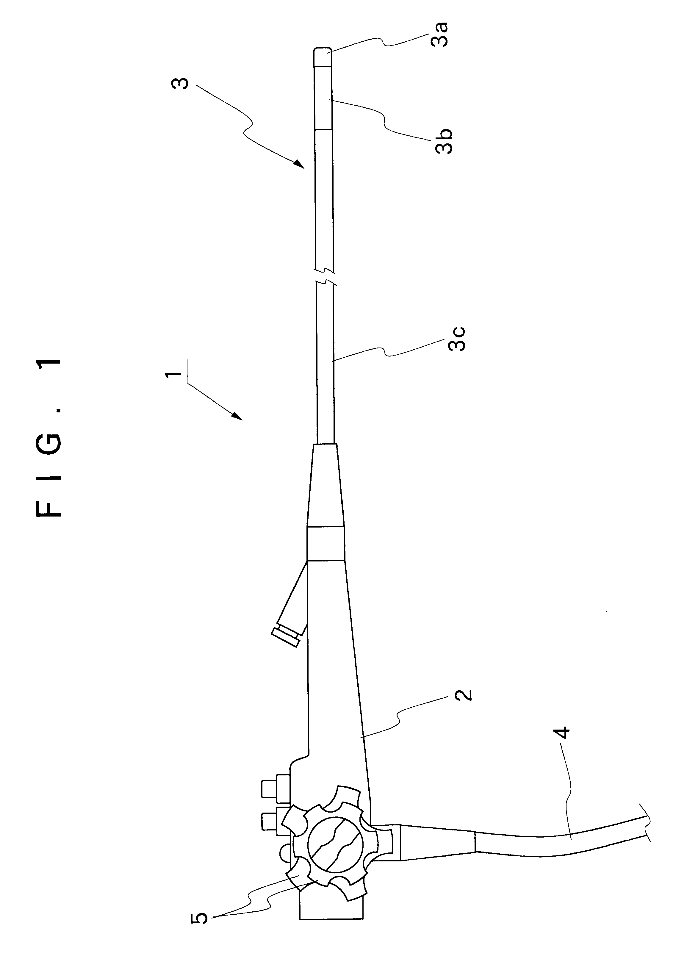
Referring first to FIG. 1, there is schematically shown the general layout of an endoscope. As seen in this figure, the endoscope 1 is largely constituted by a manipulating head assembly 2, an elongated insertion instrument 3 which is extended out on the front side of the manipulating head assembly 2 for insertion into a patient's body cavity or the like, and a universal cable which is led out on the rear side of the manipulating head assembly 2. For the functions required, the insertion instrument 3 is composed of, from its fore distal end, a rigid tip end section 3a, an angle section 3b and a flexible body section 3c.

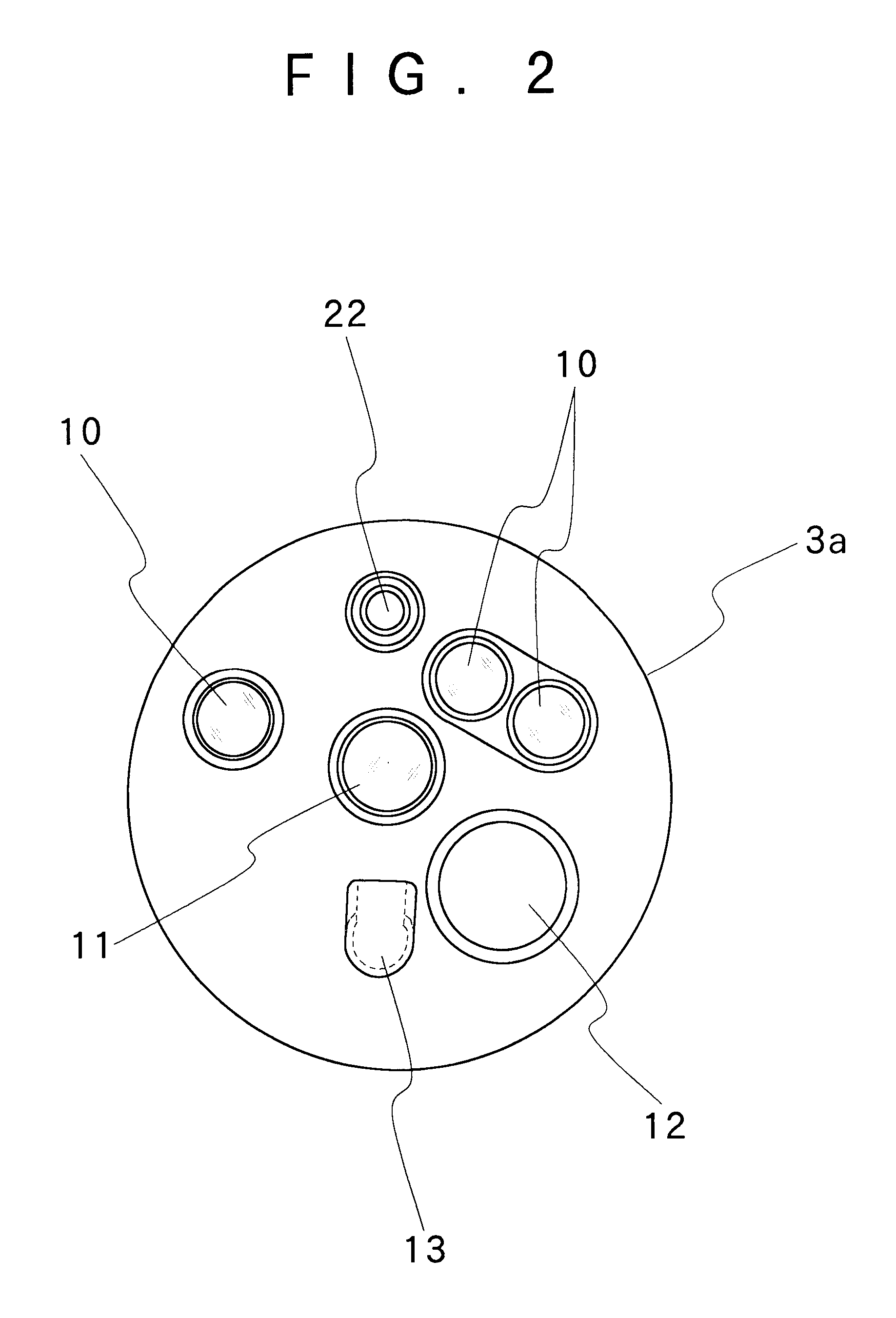
The rigid tip end section 3a is housed in a casing of a rigid material and provided with illumination windows 10, an observation window 11, an outlet opening 12 of a biopsy channel, a washer nozzle 13 and so forth. In this instance, as shown in the drawing, the illumination windows 10 are normally provided at a plural number of positions on the opposite sides of the o...


PUM


Abstract

An endoscope having an objective lens drive mechanism for an optical objective lens system, which is incorporated into a rigid tip end section of an elongated insertion instrument of the endoscope and provided with at least two movable lens groups which are movable in the direction of optical axis of the objective lens system. Ring members are connected to movable lens frames which support the respective movable lens groups. A cam pin is projected radially on the inner periphery of each ring member, while a cam shaft which is formed with a plural number of cam grooves on its circumferential surface is located in parallel relation with the optical objective lens system. The members are fitted on the cam shaft with the respective cam pins in engagement with the cam grooves. The cam shaft is rotated in forward and reverse directions by a drive means.

Description

1. Field of the ArtThis invention relates to an endoscope for use in medical examinations, and more particularly to an endoscope which is provided with an objective lens drive mechanism to move by remote control a plural number of lens groups of an optical objective lens system, which is incorporated into an observation window on a rigid tip end section of an elongated insertion instrument of the endoscope, for example, for adjustment of at least focal depth, image magnification rate or view field angle.2. Prior ArtGenerally, endoscopes which are in use for medical purposes are largely constituted by a manipulating head assembly to be gripped and manually operated by a hand of an operator, an elongated insertion instrument extended on the front side of the manipulating head assembly for insertion into a body cavity of a patient, and a universal cable which is led out from the manipulating head assembly and disconnectibly connected to a light source. For its functions, the elongated ...

Claims


Application Information

Patent Timeline
Patent Type & Authority Patents(United States)
IPC IPC(8): A61B1/00G02B23/24G02B23/26
CPCA61B1/00188G02B23/2438
Inventor MITSUMORI, NAOTAKE
Owner FUJI PHOTO OPTICAL CO LTD
Why Eureka
Try Eureka