High pressure product swivel

a technology of high-pressure products and swivels, which is applied in the direction of fluid pressure sealed joints, adjustable joints, other medical devices, etc., can solve the problems of swivel components, i, inner and outer housings, and large weight of swivel components

Inactive Publication Date: 2002-09-17
SOFEC
View PDF35 Cites 21 Cited by
  • Summary
  • Abstract
  • Description
  • Claims
  • Application Information

AI Technical Summary

Benefits of technology

A primary object of the invention is to provide a fluid swivel arrangement that is capable of flowing high pressure product through it without danger of product leaking past dynamic seal grooves formed between the inner and outer housings.
Another object of the invention is to provide a sealed fluid joint with an internal design that minimizes dynamic extrusion gap growth as a function of internal fluid pressure by transferring component deformation from the dynamic seal gap to the static seal gap while taking advantage of the fact that static product seals can tolerate larger extrusion gaps without failure.
Another object of the invention is to provide a sealed fluid joint with an inner housing and a coaxial middle and outer housing rings which provide two concentric toroidal chambers, one formed between the inner housing ring and the middle housing ring, the second between the middle housing ring and the outer housing ring where both toroidal chambers are fluidly in communication with each other through holes in the middle housing ring thereby allowing the pressurized product fluid to flow from the inlet to the outlet.
Another object of the invention is to provide a sealed fluid joint with an inner housing and middle and outer housing rings where the middle and outer housing rings are arranged and designed to rotate together but can move radially away from each other as a function of increasing internal fluid pressure.
The objective of the arrangement is to maintain the dynamic extrusion gap at its initial or zero pressure width even at high internal fluid pressures. Because dynamic seals are more likely to fail than are static seals when subject to pressure, maintaining a small dynamic extrusion gap minimizes the likelihood of product leaking past the dynamic seals. Maintaining the dynamic extrusion gap at its initial width using this arrangement also eliminates the effect of radial deformation on the bearing performance, because bearing plates are provided which are bolted to the middle housing ring and subject to the same effect.
According to another aspect of the invention, a swivel stack is provided with a fixed swivel stack base and one or more swivels having their inner housings each fixed to each other and to the fixed stack base. Each swivel has an inlet at its inner housing connected to an inlet of the stack base by means of a floating spool with a pressure balanced connection at both the swivel and at the base. Such pressure balancing of the spool at the base and the swivel inner housing prevents high pressure fluid induced forces and thermal induced forces from being transferred from the spool to the swivel as would arise with a simple stab seal connection. Providing a floating spool with a pressure balance connection results in a coupling where substantially no pipe loads are transferred to the swivel as would occur with a rigid pipe connection. Furthermore, providing a floating spool minimizes the size of the inner housing, because it has a small profile when compared to bolted flange. A small spool size minimizes the total weight of the swivel stack. The floating spool also reduces the loads on the swivel stack base and the size of the swivel itself.

Problems solved by technology

Swivel component deformation has been the subject of much effort by prior developers.
With high pressures, however, the swivel components, i.e., the inner and outer housings, become so large and heavy that they are disadvantageous from weight, cost, handling and size standpoints and without necessarily achieving the desired gap control.
Metal to metal contact of the anti-extrusion ring with the annular surface of the inner ring can cause friction and scoring problems during operation.
Another problem inherent in high pressure production swivels is that at extremely high pressures, e.g., 5000 psi and above, a fixed connection of the inlet spool to the inner housing can cause pipe loads and a seal stab connection can cause forces to be applied to the inner housing as a result of the pressure acting at the connection.

Method used


Image

  • High pressure product swivel
  • High pressure product swivel
  • High pressure product swivel

Examples


Embodiment Construction

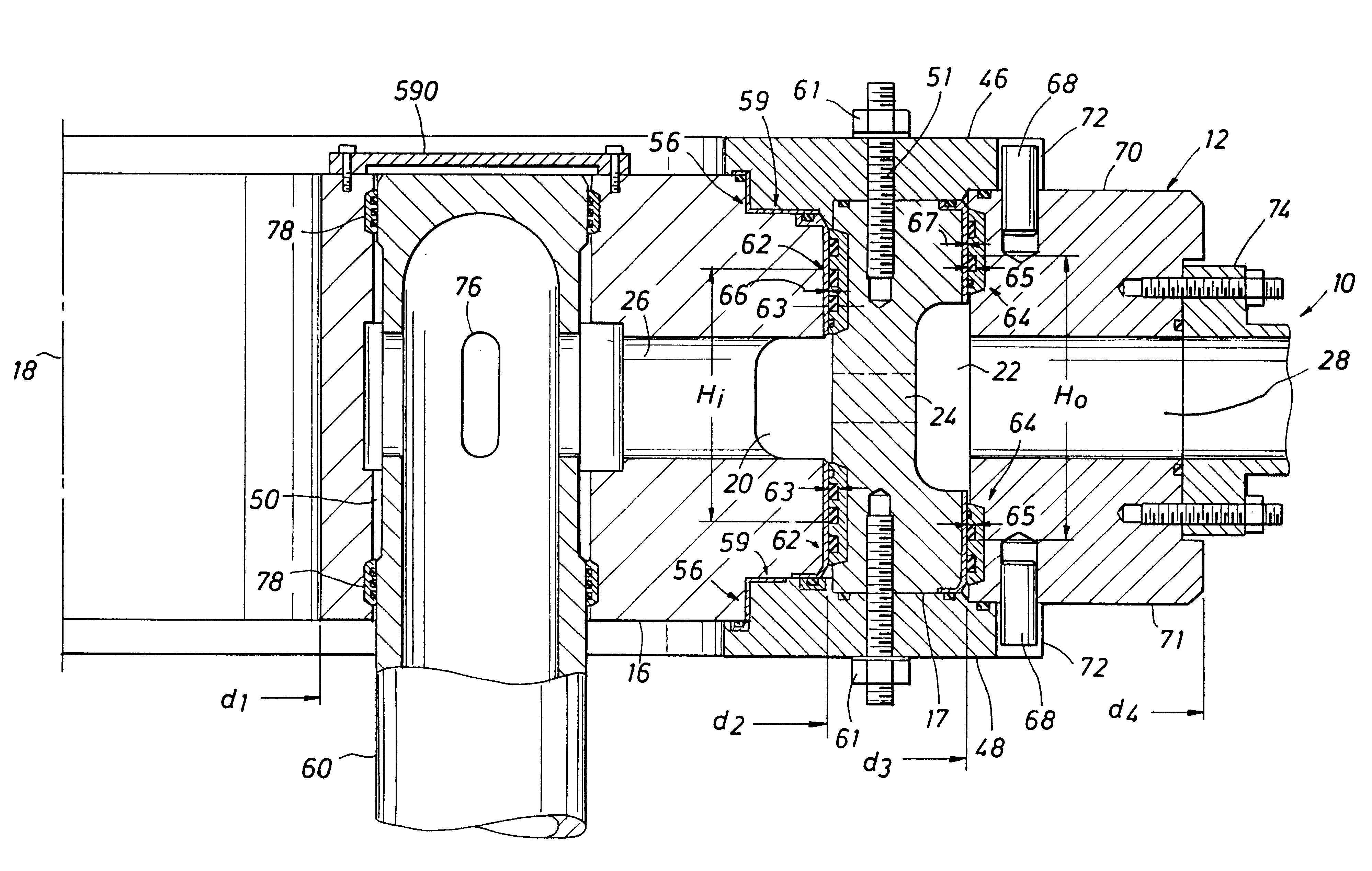
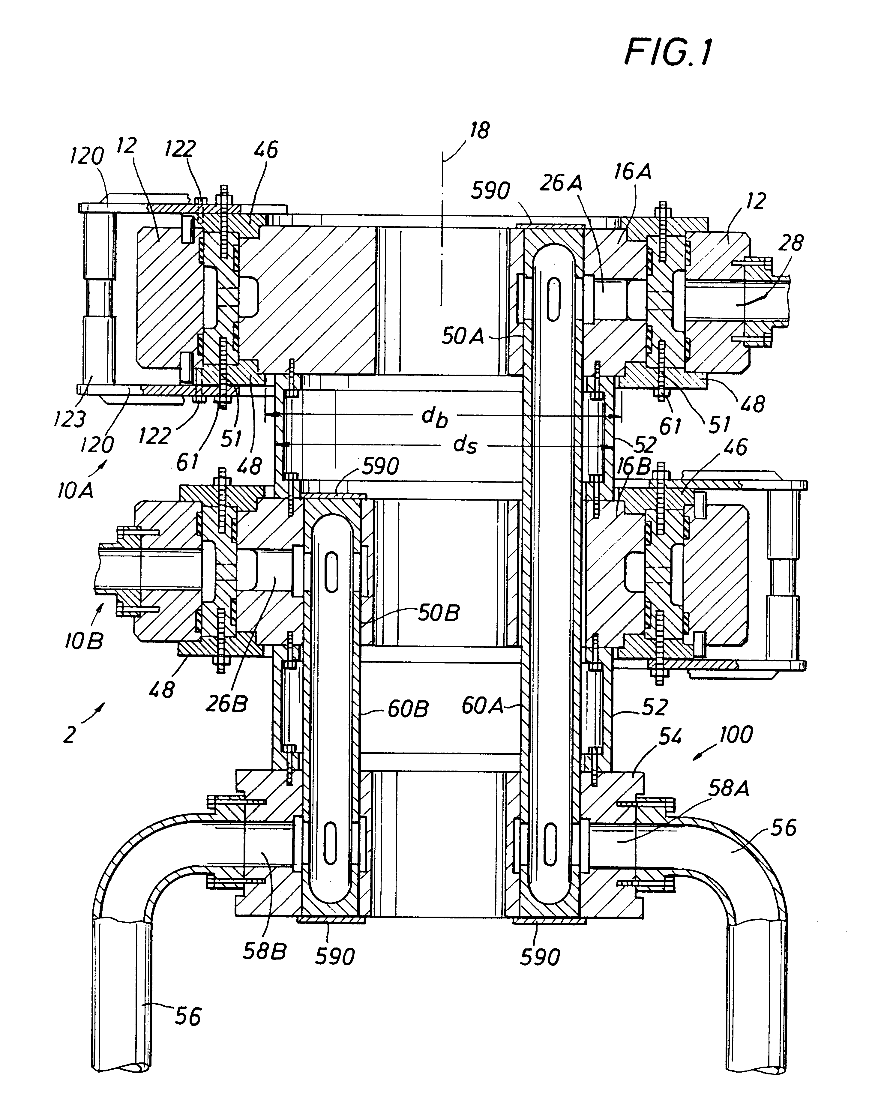
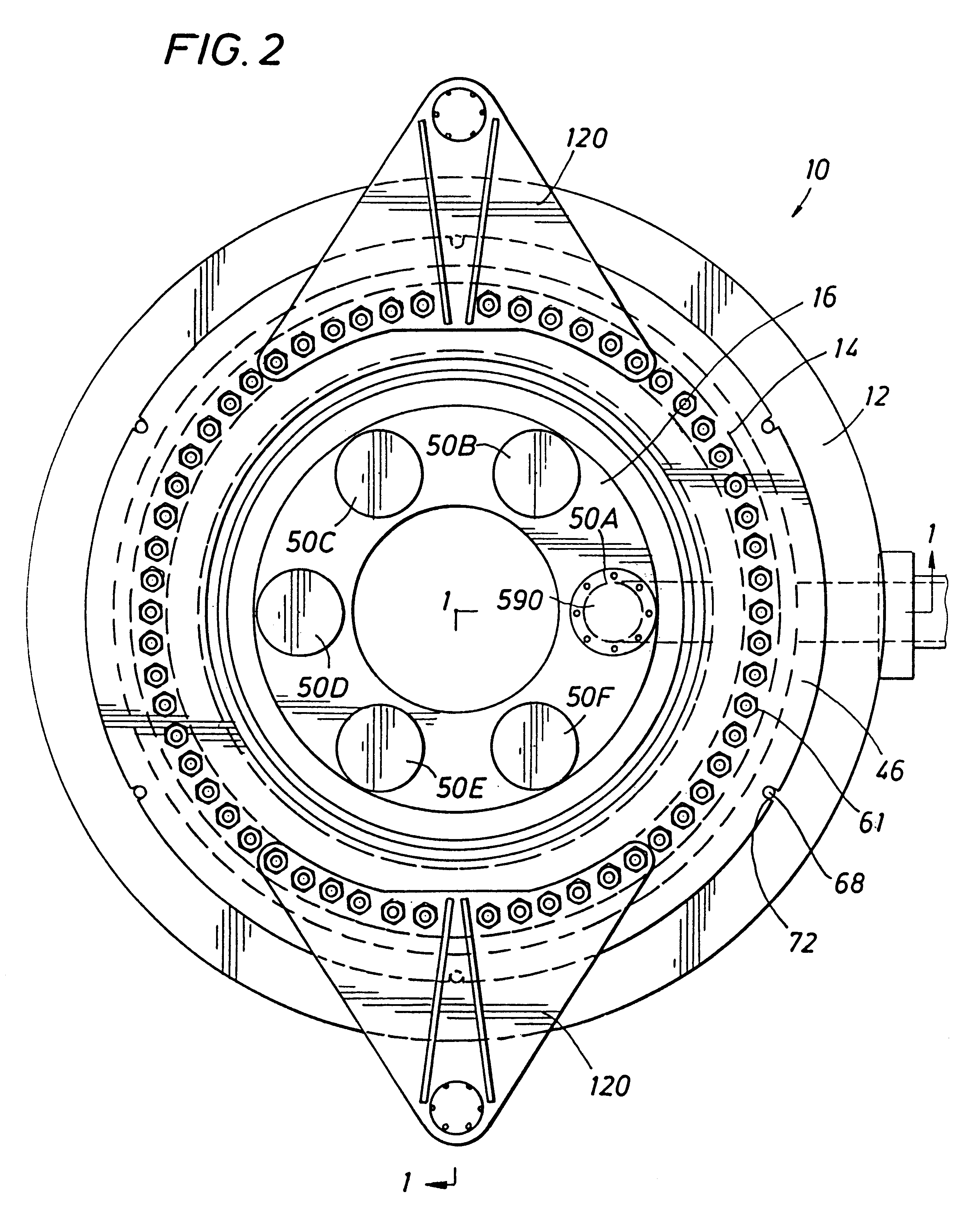
FIG. 1 illustrates a stack of swivels stacked on top of each other according to the invention. Two swivels, 10A, 10B (also called sealed fluid joints herein) are shown stacked atop fixed swivel base 100. Only two swivels are shown for illustrative purposes in FIG. 1, but as FIG. 2 shows, six inner housing bores 50A, 50B, . . . 50F in each inner housing 16A . . . 16B accommodate six swivels stacked on top of each other. Of course, more or less than six swivels can be stacked. As shown in FIG. 1, each inner housing 16 (e.g., 16A of the top swivel, 16B of the bottom swivel) is secured to another inner housing by means of a respective swivel connector 52. The bottom most swivel in the stack (e.g., as shown in FIG. 1) connects its inner housing 16B to a base housing 54 of swivel stack base 100 through a swivel connector 52.

The swivel stack base 100 is fixed to a substantially geostationary point (not shown) of an offshore mooring terminal. For a turret moored system, for example, the bas...


PUM


Abstract

A production swivel with passive control of dynamic seal gap width using internal swivel pressure. The swivel includes inner and outer housings with a middle housing which transfers, component deformation due to fluid pressure from the dynamic sealing interface to the static sealing interface. The outer housing and inner housing rotate together, but the outer housing is free to expand radially outward from the middle housing with increasing fluid pressure. A floating riser spool is pressure balanced at the connection to the inner housing and to a fixed swivel stack base. Swivels are stacked with a swivel connector / spool and upper and lower mounting rings cooperatively dimensioned so that access to seals can be obtained while the swivels remained stacked without the use of overhead cranes or other lifting points than the swivel being serviced.

Description

1. Field of the InventionThis invention relates in general to equipment for transferring fluids. In particular, the invention relates to a fluid swivel joint and a swivel stack assembly adapted for transferring fluids between tankers, storage vessels and the like and one or more conduits beneath the ocean surface. The fluid of the swivel may be product such as hydrocarbons to be transferred from the seabed to a vessel or may be water or gas to be transferred from the vessel to the seabed for well stimulation.Still more particularly, the invention relates to a sealing arrangement for a fluid swivel joint which uses the pressure of the fluid flowing through the joint to substantially prevent seal glands, and extrusion gaps in which dynamic seals are placed, from enlarging as a function of high pressure of the fluid commonly encountered on offshore loading terminals for oil and gas tankers. The invention also relates to an arrangement by which a spool is coupled between a swivel joint ...

Claims


Application Information

Patent Timeline
Patent Type & Authority Patents(United States)
IPC IPC(8): F16L39/00F16L39/06A61M39/00F16L39/04
CPCF16L39/04F16L39/06Y10S285/90
Inventor MONTGOMERY, MARSHALL N.ROY, STEPHANE
Owner SOFEC
Why Eureka
Try Eureka