Conveyor system

a conveyor system and belt technology, applied in the field of conveyor systems, can solve the problems of limited heat resistance and corrosion resistance, shorten the life of the conveyor belt, and the gear is apt to produce dust and particles

Inactive Publication Date: 2002-09-17
TOKYO ELECTRON LTD
View PDF8 Cites 381 Cited by
  • Summary
  • Abstract
  • Description
  • Claims
  • Application Information

AI Technical Summary

Benefits of technology

The carrying device according to the third invention is provided with the frog leg type arm capable of exercising th...

Problems solved by technology

Belts, such as steel belts, have limited heat resistance and corrosion resistance and the hot, corrosive atmosphere in the processing chamber short...

Method used


Image

  • Conveyor system
  • Conveyor system
  • Conveyor system

Examples


first embodiment

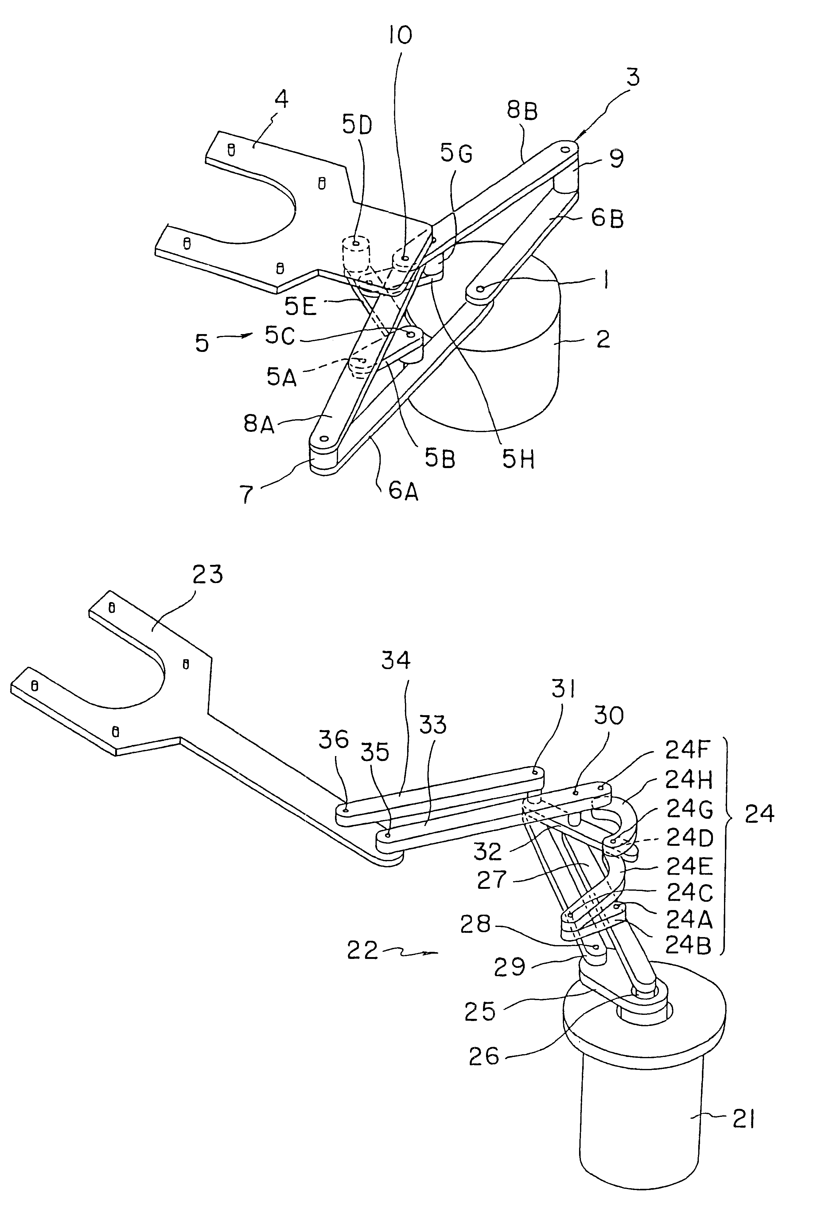
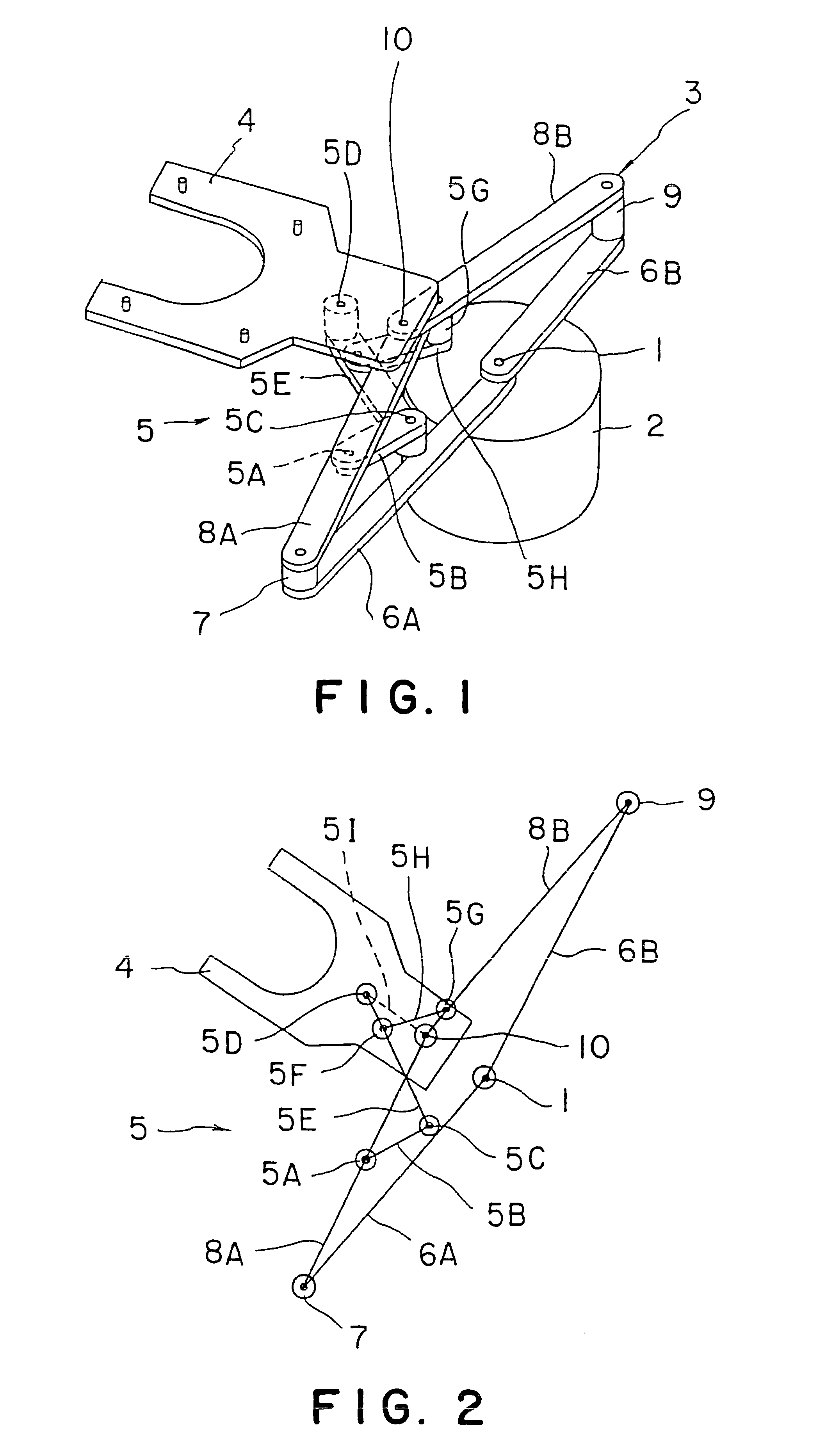
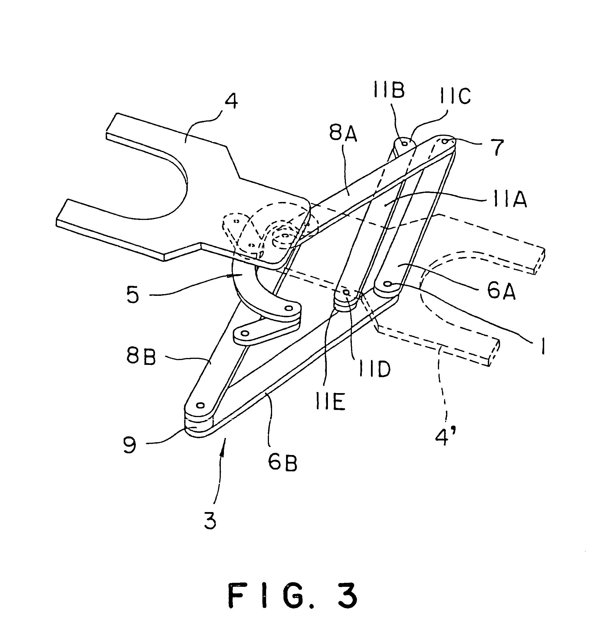
Referring to FIGS. 1 and 2, a carrying device in a first embodiment according to the present invention includes a drive shaft 1 formed by coaxially combining first and second drive shafts, not shown, a support member 2 supporting the drive shaft 1 in its central part and housing a driving device for driving the drive shaft 1, a frog leg type arm 3 having a base end part connected to the drive shaft 1 supported on the support member 2, a wafer holder 4 connected to a front end part of the frog leg type arm 3, and a posture maintaining linkage 5 for restricting the turning of the wafer holder 4 to maintain the wafer holder 4 always in a fixed posture. The first drive shaft of the drive shaft 1 is a hollow shaft and the second drive shaft is extended through the first drive shaft. The first and the second drive shaft are connected with a driving device and are driven for turning in the normal direction and the reverse direction (in the opposite directions), respectively. The frog leg t...

fourth embodiment

Referring to FIGS. 7 to 9, a carrying device in a fourth embodiment according to the present invention includes a drive shaft 26 formed by coaxially combining first and second drive shafts, not shown, (hereinafter referred to simply as "drive shaft"), a support member 21 supporting the drive shaft 26 in its central part and housing a driving device for driving the drive shaft 26, a parallel linkage type arm 22 having a base end part connected to the drive shaft 26 supported on the support member 21, a wafer holder 23 connected to a front end part of the parallel linkage type arm 22, and a posture maintaining linkage 24 for controlling the posture of the parallel linkage type arm 22 to maintain the wafer holder 23 always in a fixed posture. The first drive shaft of the drive shaft 26 is a hollow shaft and the second drive shaft is extended through the first drive shaft. The first and the second drive shaft are interlocked with a driving device and are driven for turning in the normal...

second embodiment

The present invention may be embodied by frog leg type carrying devices shown in FIGS. 12 to 15. The frog leg type carrying devices shown in FIGS. 12 to 15 are capable of exercising the same functions and effects as those exercised by the carrying devices in the first and the

The carrying device shown in FIG. 12 includes a frog leg type arm 32, a wafer holder 33, and a posture maintaining linkage 34 interconnecting the wafer holder 33 and the frog leg type arm 32. The frog leg type arm 32 includes a first drive arm 32A, a second drive arm 32B, a first front arm 32C and a second front arm 32D. The frog leg type arm 32 is connected to the wafer holder 33 by a joint 35.

As shown in FIG. 12, the posture maintaining linkage 34 includes a first link 34B having one end part pivotally connected to the first front arm 32C by a pivot 34A, a second link 34E having one end part pivotally connected to the other end part of the first link 34B by a pivot 34C and the other end part pivotally connecte...


PUM


Abstract

In most cases, a hot, corrosive atmosphere is created in, for example, a semiconductor wafer processing chamber. When an arm including belts, such as steel belts, is moved into such a semiconductor wafer processing chamber, the belts are exposed to the hot, corrosive atmosphere. Belts, such as steel belts, have limited heat resistance and corrosion resistance and the hot, corrosive atmosphere in the processing chamber shortens the life of the belts. A carrying device of the present invention has a frog leg type arm (3) and a wafer holder (4) connected to the frog leg type arm (3). The wafer holder (4) is pivotally connected to front end parts of a first front arm (8A) and a second front arm (8B) by coaxial joints (10). The wafer holder (4) is linked to the first front arm (8A) and the second front arm (8B) by a posture maintaining linkage (5) including two antiparallel linkages capable of controlling the turning of the wafer holder (4) relative to the first and the second front arms (8A, 8B).

Description

TECHNICAL FIELDThe present invention relates to a carrying device employed in, for example, a semiconductor device fabricating system to carry semiconductor wafers, i.e., workpieces.BACKGROUND ARTA conventional carrying device of this kind is used, for example, for carrying semiconductor wafers between a wafer storage chamber and a wafer processing chamber. Known carrying devices of this kind include those provided with a frog leg type arm and those provided with a parallel link type. A carrying device provided with a frog leg type arm has, for example, a pair of drive arms having base end parts connected to a drive shaft, a pair of front arms connected to front end parts of the drive arms by joints, respectively, and a wafer holder connected to front end parts of the front arms. For example, the front end parts of the pair of front arms are connected to the wafer holder by two rotating drums, i.e., upper and lower rotating drums. Two steel belts, i.e., upper and lower steel belts, ...

Claims


Application Information

Patent Timeline
IPC IPC(8): B25J9/10H01L21/677H01L21/67H01L21/687B25J9/06B25J18/02
CPCB25J9/1065B25J9/107H01L21/67742H01L21/687Y10T74/20329Y10S414/13Y10T74/20305H01L21/68
Inventor SAEKI, HIROAKIKONDOH, KEISUKE
Owner TOKYO ELECTRON LTD
Why Eureka
Try Eureka