Computer module mounting system and method

a technology for mounting systems and computers, applied in the direction of electrical apparatus casings/cabinets/drawers, furniture parts, instruments, etc., can solve the problems of large computer system cost, difficult management and support of cable systems, and high cost of cables connecting these units, so as to improve cable management, increase the ease of mounting of modules, and the effect of greater width

Inactive Publication Date: 2002-09-17
HEWLETT-PACKARD ENTERPRISE DEV LP +1
View PDF14 Cites 50 Cited by
  • Summary
  • Abstract
  • Description
  • Claims
  • Application Information

AI Technical Summary

Benefits of technology

According to one aspect of the invention a computer module mounting system includes an improved rack having features for grounding the computer system to the rack. In another embodiment, the rack provides improved cable management. In one embodiment, the rack includes a front portion for supporting computer modules and a rear portion have a greater width use in positioning cables so that computer modules can be accessed. In another embodiment, the rack includes an improved rail and shelf support system for increasing the ease with which modules are arranged within the racks. In yet another embodiment, the rack includes passages for use in routing cables between computer modules supported in another rack. In yet another embodiment, the racks can be used to create large computer systems having routers centrally placed in order to minimize cable distances. The result is improved ease of installation, service, upgrade and scalability.

Problems solved by technology

Cables connecting these units are expensive and extensive cable connections can make a larger computer system cost prohibitive.
Additionally, extensive cable connections can make the cable system difficult to manage and support.
Furthermore, such cable connections also introduce greater amounts of electromagnetic interference into the system.
Industry standards, however, do not address all of the needs of the industry including those factors related to ease of installation, service, upgrade and scalability of computer systems.
Installation, service and upgrade of a commercial computer system can be a protracted and cumbersome process.
Installation may require time consuming placement of supports within the standard racks.
Service can be further complicated because cables have traditionally been left unorganized; even ancillary cables must often be disconnected from the system to access a computer module or must be repositioned using ad hoc means.
The difficulty of removing a module from the rack can be compounded by the increased weight of the element.
In some cases this may require extensive removal and re-assembly of additional portions of sub-floor.
Another problem is the lack of alignment common to these modular computer systems.
Modules are typically difficult to align and install into the rack.
Modules will typically be positioned within racks providing poor access to the module.
This can slow the installation, service, and upgrade processes making larger systems from these components less desirable.
This is also one cause of poor field serviceability.
Proper positioning, grounding and servicing of modules is often either not done, poorly done, or improperly done.

Method used


Image

  • Computer module mounting system and method
  • Computer module mounting system and method
  • Computer module mounting system and method

Examples


Embodiment Construction

In the following detailed description of the preferred embodiments, reference is made to the accompanying drawings that form a part hereof, and in which is shown by way of illustration specific embodiments in which the invention may be practiced. It is to be understood that other embodiments may be utilized and structural changes may be made without departing from the scope of the present invention.

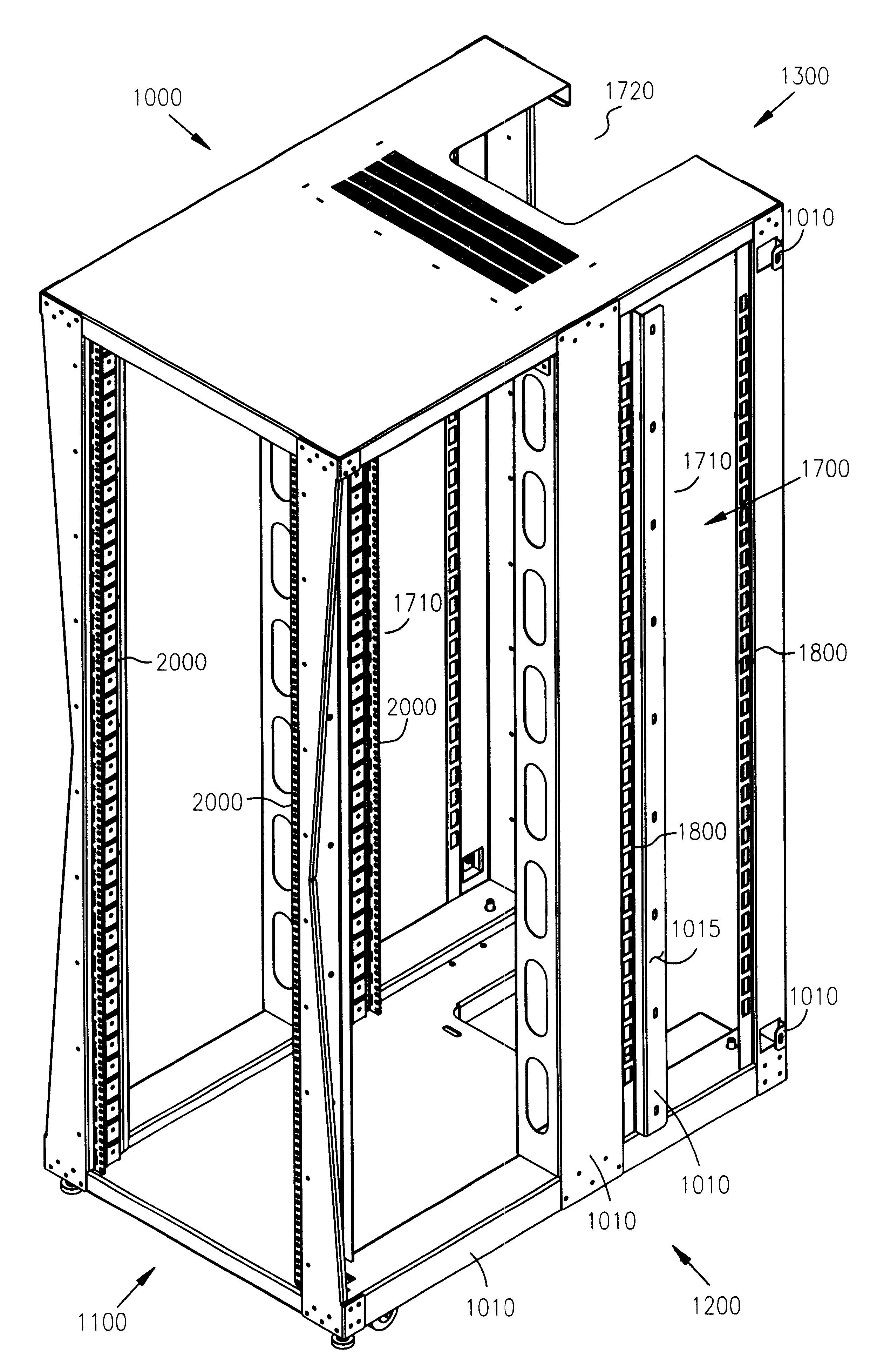
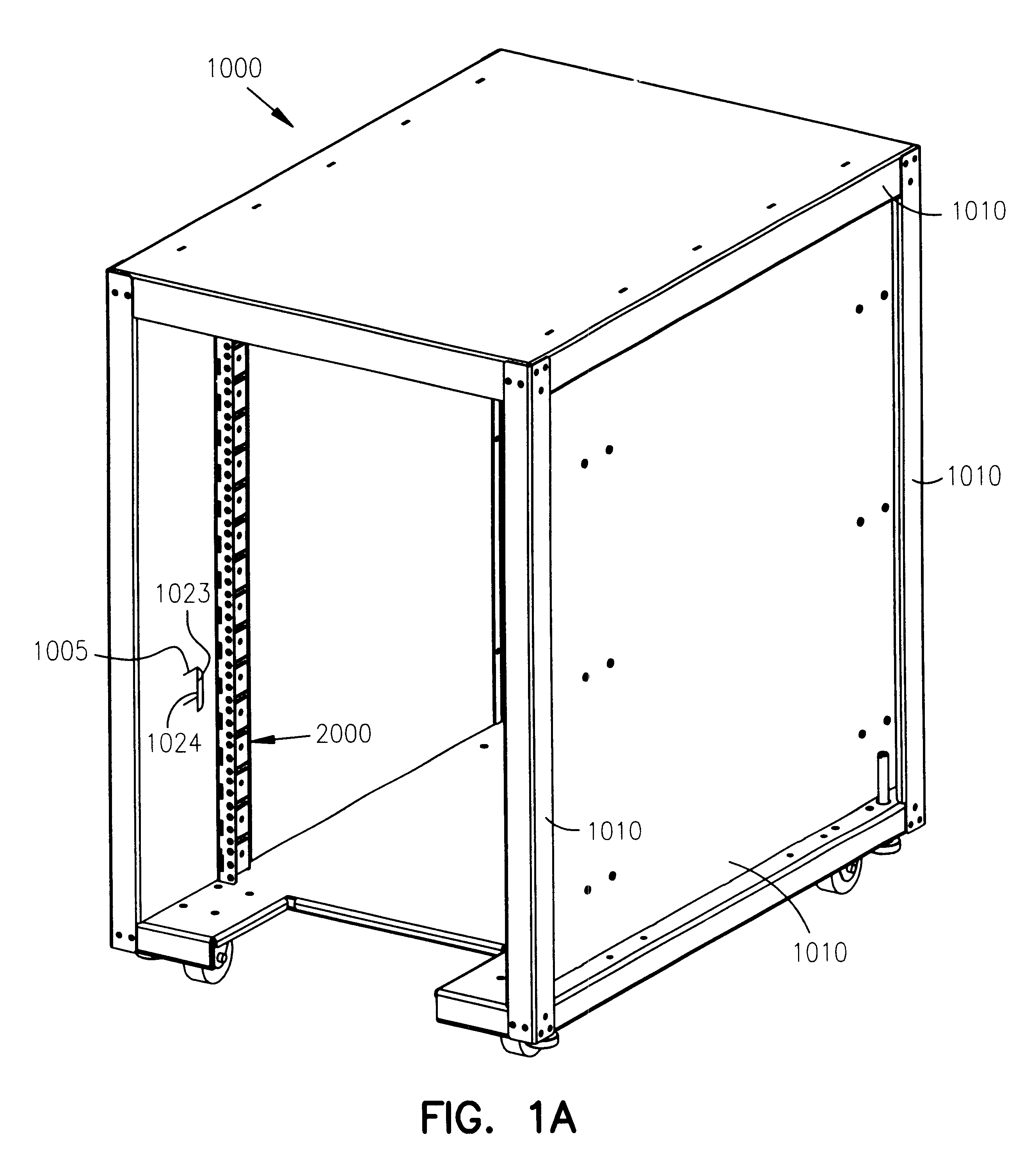
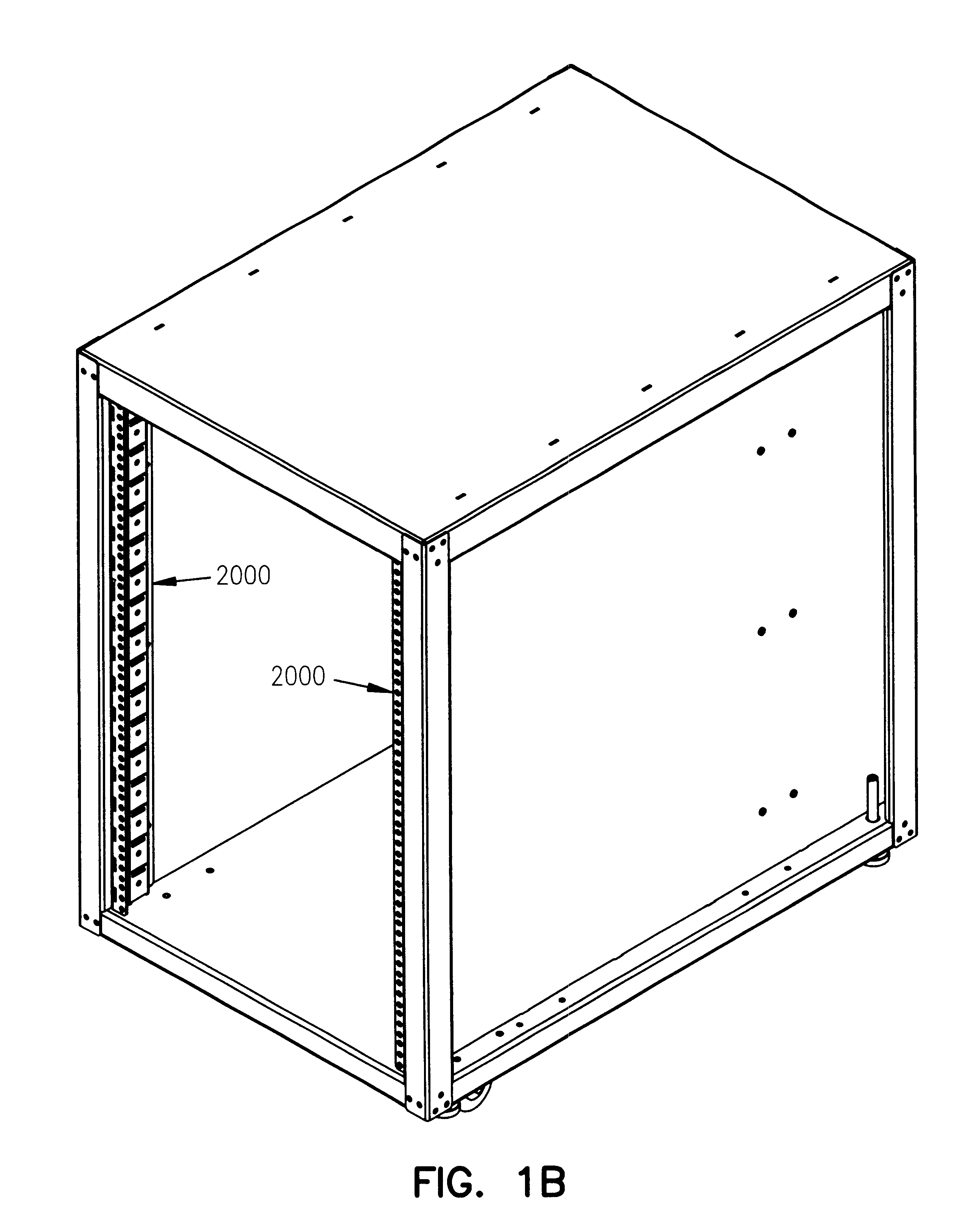
FIGS. 1a and 1b illustrate an embodiment of an improved computer rack 1000 for increasing the ease with which commercial computer systems are installed, serviced, upgraded and scaled. In one embodiment, the improved rack 1000 includes a first conductive feature 1005 for electrically coupling a computer module supported within the rack 1000 so that the first conductive feature 1005 provides a path to ground from the computer module to the rack 1000. An advantage of such a rack 1000 is the ability to eliminate grounding of computer modules external to the rack 1000 and provides for the grou...


PUM


Abstract

A rack including a rail for supporting a computer module and a grounding element electrically coupled to the rack and positioned to electrically contact a computer module inserted in the rack such that the grounding element provides a path to ground. The grounding element can be an arcuate bracket attached to the rail to make contact with a side of the computer module. The grounding element can be a conductor extending from the rack and positioned to make contact with a side of the computer module. The rack can include a wider section which provides a cabling channel and a member on the rack for mechanically coupling the rack to an adjacent rack. The rack can include at least one passage for allowing a cable to pass through the rack to an adjacent rack and a cable organizer for maintaining placement of at least one cable routed through the passage.

Description

This invention relates to computer hardware, and in particular to a computer module mounting system and method for a scalable computer system.Commercial use computer systems typically include computer modules resting on a special sub-floor allowing for cable routing and grounding beneath the floor surface. In some cases, computer modules are placed in commercial computer racks resting on the sub-floor.Industry standards dictate certain design criteria for the modules and for the racks such as a standard hole template for used in racks for supporting these computer modules. Computer modules complying with these industry standards are typically used in existing racks to build smaller scale computer systems.Achieving higher CPU density using these building blocks is inhibited, in part, by a number of factors related to the configuration of these elements. Cables connecting these units are expensive and extensive cable connections can make a larger computer system cost prohibitive. Addi...

Claims


Application Information

Patent Timeline
Patent Type & Authority Patents(United States)
IPC IPC(8): G02B6/44
CPCG02B6/4471G02B6/4452
Inventor FRANZ, PERRY D.GLANZMAN, JEFFREY MARKCOLLINS, DAVID R.DEAN, STEVE J.MCCANN, TIMOTHY S.
Owner HEWLETT-PACKARD ENTERPRISE DEV LP
Why Eureka
Try Eureka