Ion-assisted magnetron deposition

a technology of magnetron and magnetron, applied in the direction of electrolysis components, vacuum evaporation coatings, coatings, etc., can solve the problems of high electric fields at target surfaces and inconsistent with low-damage deposition requirements, and achieve the effect of prolonging operation

Inactive Publication Date: 2002-09-24
KAUFMAN & ROBINSON
View PDF3 Cites 49 Cited by
  • Summary
  • Abstract
  • Description
  • Claims
  • Application Information

AI Technical Summary

Benefits of technology

Yet another object of the present invention is to provide an ion-assisted magnetr

Problems solved by technology

Those skilled in plasma physics will recognize that operation with current neutralization will not avoid a potential difference between the ion beam and a normal

Method used


Image

  • Ion-assisted magnetron deposition
  • Ion-assisted magnetron deposition
  • Ion-assisted magnetron deposition

Examples


specific examples

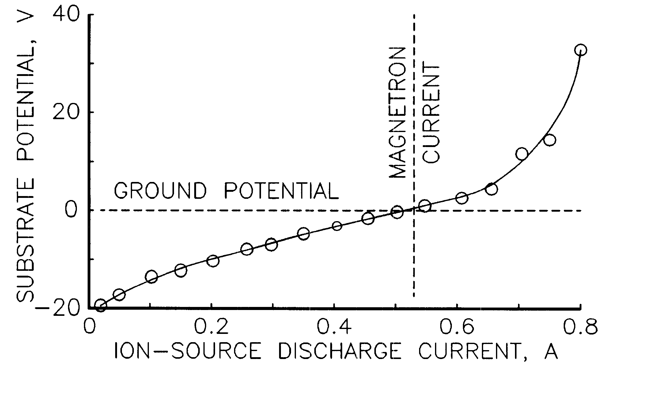
One configuration of FIG. 8 that was tested used the circuit diagram shown in FIG. 10 and the spatial configuration indicated in FIG. 11. The magnetron used was a two-inch diameter Torus Sputter Source marketed by Kurt J. Lesker Company, Clairton, Pa. The ion source was the Mark I End-Hall Ion Source marketed originally by Commonwealth Scientific Corporation, Alexandria, Va., and presently marketed by Veeco Instruments Inc., Plainview, N.Y. This ion source is normally supplied with either a hot-filament or a hollow-cathode type of cathode-neutralizer, but neither was used in this test. The spacings between the magnetron, ion-assist source, and deposition substrate are shown with the magnetron and ion-assist source indicated approximated to scale. An electrically isolated deposition substrate is not necessary for all embodiments of the invention, but was included as a diagnostic in the testing.

For the test results shown in FIG. 12, the only gas introduced into the apparatus was 100 s...


PUM

PropertyMeasurementUnit
Currentaaaaaaaaaa

Abstract

In accordance with an embodiment of the present invention, apparatus for ion-assisted magnetron deposition takes a form that includes a magnetron, a deposition substrate displaced from the magnetron, and an ion source also displaced from the magnetron and located so that the ion beam from the ion source is directed at the deposition substrate. The ion source is operated without an electron-emitting cathode-neutralizer, the electron current for this function being provided by electrons from the magnetron. In one specific embodiment, the ion source is operated so that the potential of the deposition substrate is maintained close to that of a common ground for the magnetron and the ion source. In another embodiment, the ion source is of the Hall-current type and the discharge current of the ion source is approximately equal in magnitude to the current of the magnetron discharge.

Description

This invention relates generally to ion and plasma technology, and more particularly it pertains to ion-assisted deposition from magnetrons wherein the ions from an ion source compact, react with, or otherwise modify the thin film deposited by a magnetron.Deposition of thin films by sputtering is widely used. The technology of magnetrons with planar targets is described by Waits in Chapter II-4 of Thin Film Processes (John L. Vossen and Werner Kern, eds.), Academic Press, New York (1978) beginning on page 131. Sputtering targets with other than planar shapes have also been used in magnetrons, as described in U.S. Pat. No. 2,146,025--Penning and in U.S. Pat. No. 3,616,450--Clarke. A related deposition technology is the use of energetic ion beams directed at sputter targets to deposit thin films on substrates as described by Harper in Chapter II-5 of the aforesaid Thin Film Processes beginning on page 131. These publications are incorporated herein by reference.The modification of thi...

Claims


Application Information

Patent Timeline
IPC IPC(8): C23C14/00C23C14/35H01J37/32H01J37/34C23C14/34
CPCC23C14/0031C23C14/3442C23C14/354H01J37/3233H01J37/3405
Inventor ZHURIN, VIACHESLAV V.KAUFMAN, HAROLD R.KAHN, JAMES R.THOMPSON, KIRK A.
Owner KAUFMAN & ROBINSON
Why Eureka
Try Eureka