Multiple layer double rotor single stator skew symmetry permanent magnet rotating motor

a permanent magnet rotating motor and double rotor technology, applied in the direction of magnetic circuit rotating parts, dynamo-electric machines, magnetic circuit shape/form/construction, etc., can solve the problems of high frequency of engine gasoline refilling, difficulty in controlling the rotating direction of the motor shaft, and need for a reduction and reverse mechanism. , to achieve the effect of simple structure, low weight and high efficiency

Inactive Publication Date: 2002-09-24
NAT CHUNG SHAN INST SCI & TECH
View PDF19 Cites 32 Cited by
  • Summary
  • Abstract
  • Description
  • Claims
  • Application Information

AI Technical Summary

Benefits of technology

A second object of the present invention is to provide a rotating motor with a simple structure, which performs a high efficient power with a low weight.
A third object of the present invention is to provide a rotating motor with a low noise, which can directly drive a motor without a speed-reducing mechanism.
A fourth object of the present invention is to provide a rotating motor with a brushless form to reduce a maintenance fee.
A fifth object of the present invention is to provide a rotating motor which is free from a Gyro effect to enhance the controllability of rotation direction.

Problems solved by technology

In a prior motor structure, a rotor is rotated in one direction, but a Gyro effect will be induced and thus it is difficult to control the rotating direction of the motor's shaft.
Disadvantages of the first structure include a big noise, a high frequency to refill the engine with gasoline, and a need for a reduction and reverse mechanism.
Besides, to drive a gasoline engine is less convenient, as compared with an electronically or electro magnetically controlled engine.
Disadvantages of the second structure include a high cost, high loading and a need for two sets of driving circuits.
A disadvantage of the third structure is difficult to control the rotating speed between a rotor and a stator.

Method used


Image

  • Multiple layer double rotor single stator skew symmetry permanent magnet rotating motor
  • Multiple layer double rotor single stator skew symmetry permanent magnet rotating motor
  • Multiple layer double rotor single stator skew symmetry permanent magnet rotating motor

Examples


Embodiment Construction

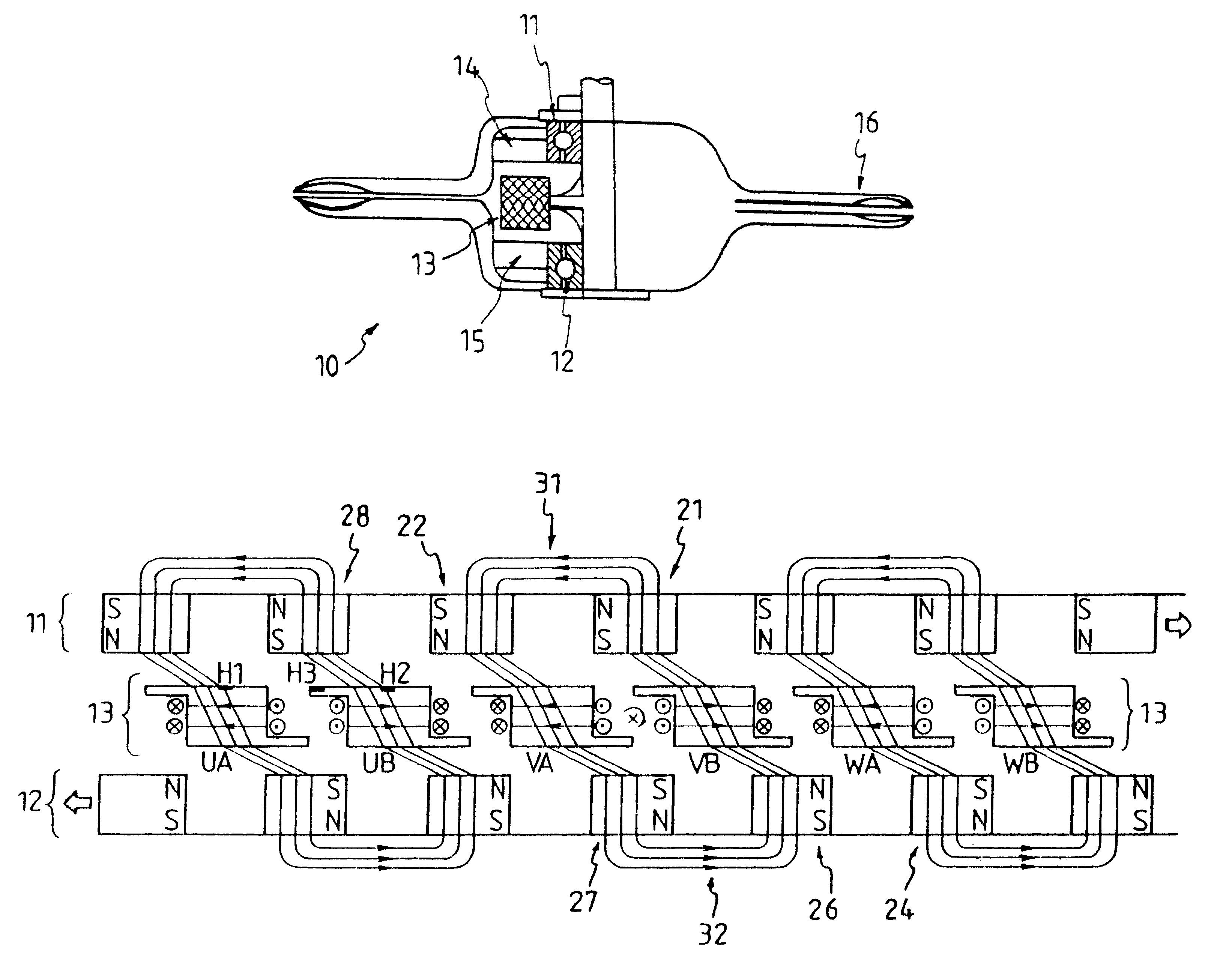
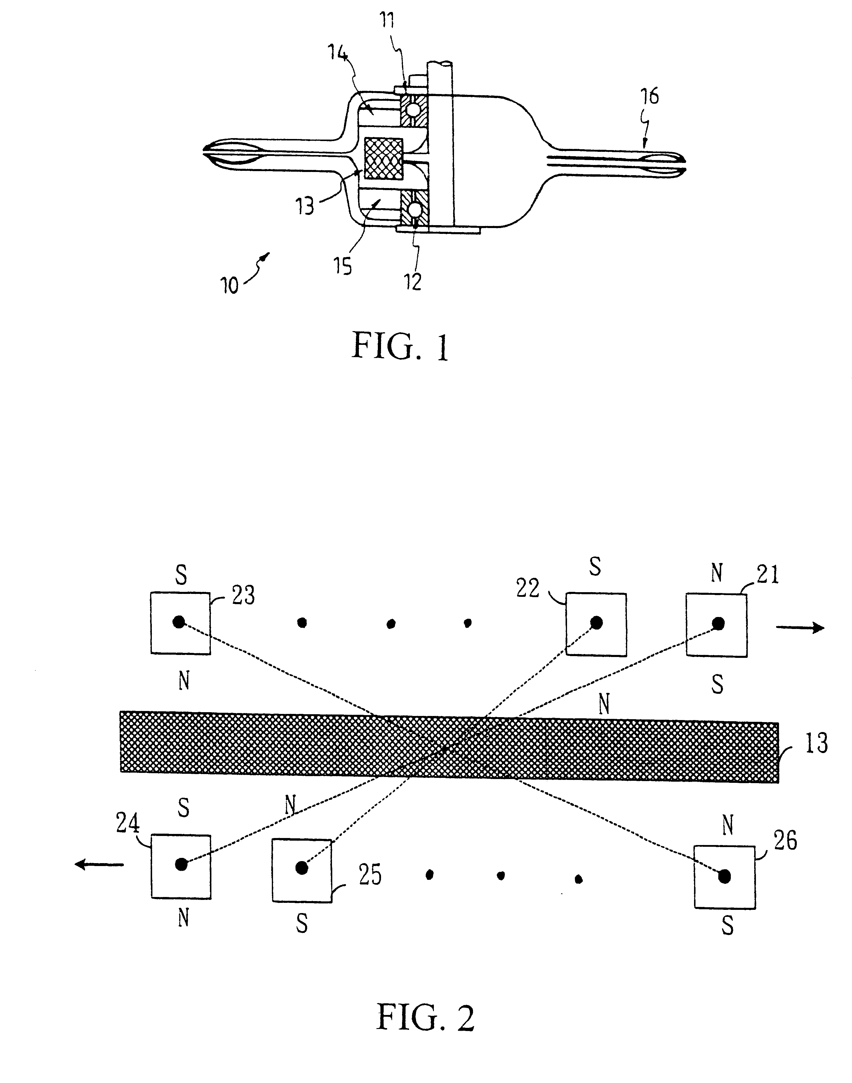
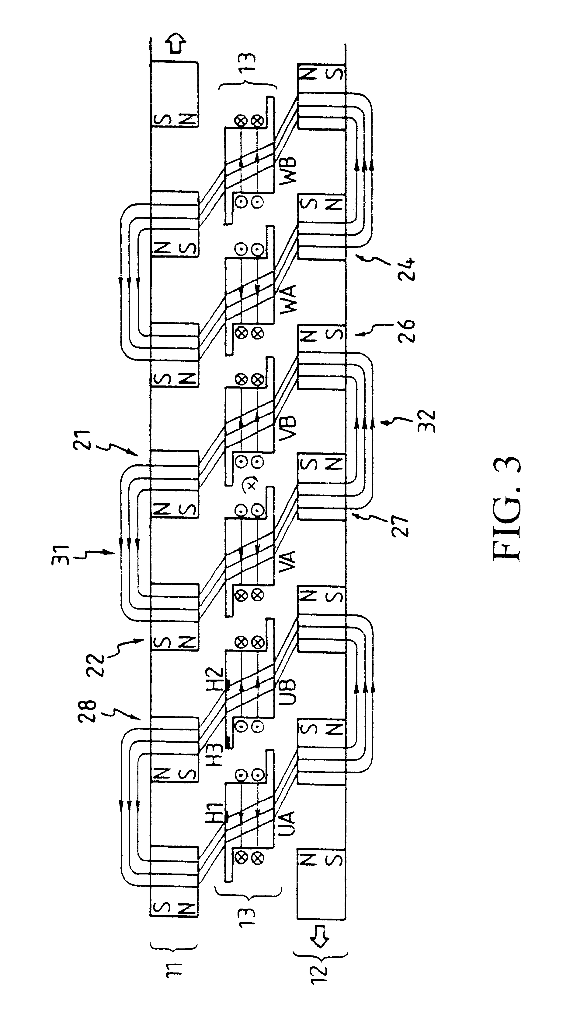
FIG. 1 shows a cross-sectional view of an embodiment of the single-stator-double-rotor (S1R2) rotating motor according to the present invention. The S1R2 rotating motor 10 comprises a bearing 11, a bearing 12, an armature layer 13, an upper-layer rotor 14, and a lower-layer rotor 15. The motor 10 is formed as a ring structure. The armature 13 is winded. Both ends of the S1R2 rotating motor 10 have their applications, such as a scissor 16 of a mower. With the torque generated by the upper-layer rotor 14 and lower-layer rotor 15, the scissor 16 will be continuously opened and closed to execute its job.

FIG. 2 shows a schematic diagram of the upper-layer rotor, the armature layer and the lower-layer rotor of the single-stator-double-rotor rotating motor according to the present invention. In FIG. 2, the upper-layer rotor 14 and lower-layer rotor 15 are embedded with a plurality of magnets respectively, and the ring structures of the upper-layer rotor 14 and lower-layer rotor 15 are spre...


PUM


Abstract

A single-stator-double-rotor rotating motor has one upper-layer rotor, one intermediate-layer armature and one lower-layer rotor. The upper-layer rotor and lower-layer rotor are embedded with the same number of magnets to form a magneto type magnetic pole, stator electrodes of the same number as the number of magnets are disposed on the intermediate-layer armature to form an electro type magnetic pole. A skew symmetry exists between an upper-layer rotor and a corresponding lower-layer rotor, and the upper-layer rotor and the lower-layer rotor are rotated in opposite directions by commutation of the current flowing through exciting coils of the stator electrodes every T / N of time, wherein T is a rotation period of the upper-layer rotor, and N is the number of the magnets.

Description

1. Field of the InventionThe present invention relates to a rotating motor, and particularly to a single-stator-double-rotor (S1R2) rotating motor.2. Description of Related ArtIn a prior motor structure, a rotor is rotated in one direction, but a Gyro effect will be induced and thus it is difficult to control the rotating direction of the motor's shaft.Another prior rotating motor includes two rotors rotating in opposite directions, and in general has three structures as follows:(1) a reduction and reverse mechanism of a gasoline engine;(2) two mutually independent motors rotating in opposite directions; and(3) a single motor, whose rotating rotors and stators are rotated in opposite directions.Disadvantages of the first structure include a big noise, a high frequency to refill the engine with gasoline, and a need for a reduction and reverse mechanism. Besides, to drive a gasoline engine is less convenient, as compared with an electronically or electro magnetically controlled engine...

Claims


Application Information

Patent Timeline
Patent Type & Authority Patents(United States)
IPC IPC(8): H02K21/12H02K16/00H02K16/02H02K21/24
CPCH02K16/02H02K21/24
Inventor CHEN, PING-HO
Owner NAT CHUNG SHAN INST SCI & TECH
Why Eureka
Try Eureka