Simple system for endoscopic non-contact three-dimentional measurement
a non-contact, three-dimensional technology, applied in the field of optical metrology, can solve the problems of inaccurate specialized measurement endoscopes, high cost, inaccurate measurement methods,
- Summary
- Abstract
- Description
- Claims
- Application Information
AI Technical Summary
Benefits of technology
Problems solved by technology
Method used
Image
Examples
second embodiment
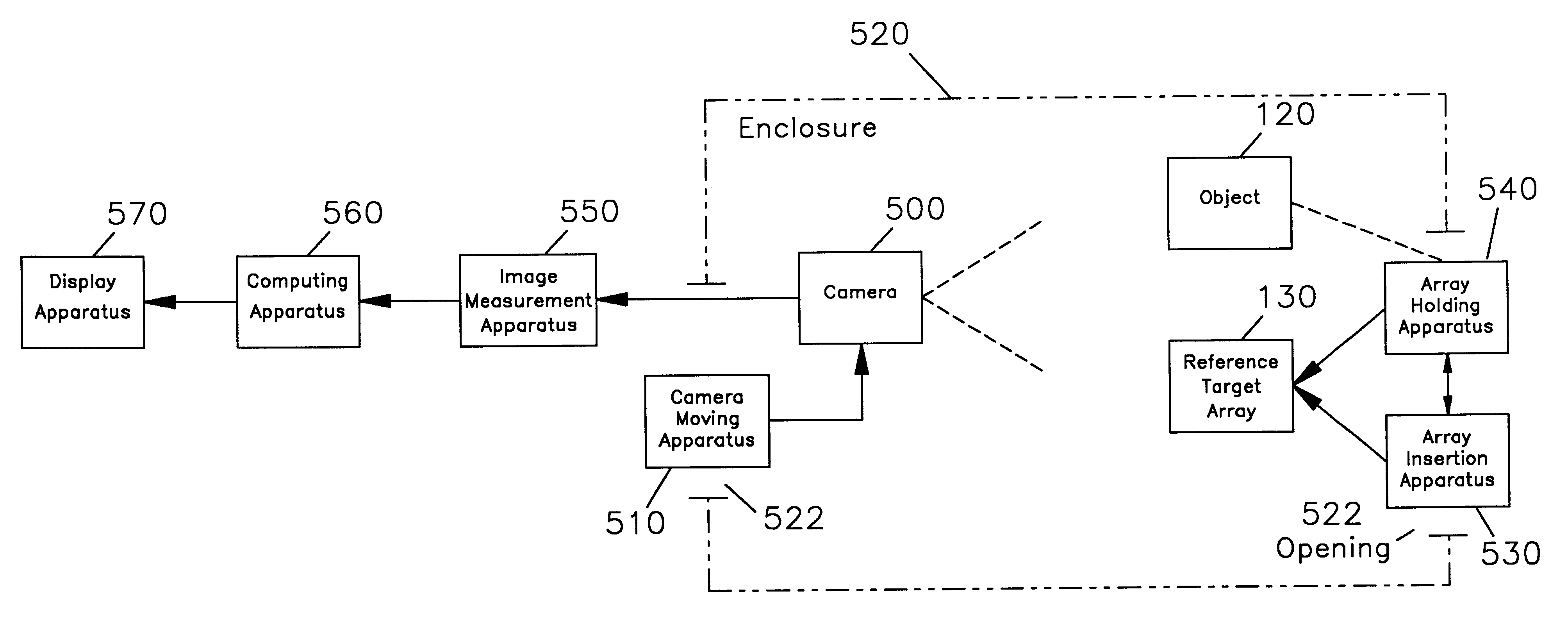
This second embodiment thus enables one to perform the new perspective dimensional measurement with a side-looking rigid borescope. The implementation shown here also demonstrates that the reference target array can be mounted through the same inspection port that serves the borescope.
If one is concerned about contact between the object of interest and target array 130, one initially inserts support wire 140 into slot 168 so that target array 130 extends into the enclosure only a small distance when support body 160 is introduced into the inspection port. One then inserts the borescope and obtains a view of the target array. One then advances both the target array and the borescope in steps, monitoring the position of target array 130 with respect to the object as the insertion process proceeds.
Support wire 140 may be circular in cross-section, as shown, or it may be polygonal, if there is no need to adjust the angular orientation of target array 130 with respect to the line of sigh...
first embodiment
Just as in the first embodiment, if the images are captured in a short exposure time one can hand hold the borescope instead of using a support body. The reference target array must be supported fixed in position with respect to the object during the time necessary to acquire both images.
4. Description of the Third Embodiment
FIG. 19 is a fragmentary perspective view depicting a third embodiment of the measurement system. This embodiment can use a substantially forward looking rigid borescope, as represented by insertion tube 402. A first position of the borescope is shown at 402 and a second position is shown at 402'. Borescope support body 160a is similar in many respects to support body 160 which is used in the second embodiment, but it also has important differences. A side elevation view of support body 160a is shown in partial cross-section in FIG. 20.
An object of interest is to be understood as being located in the vicinity of reference target array 130. Once again, array 130 ...
third embodiment
To use this third embodiment, one first inserts the proximal end of support wire 140 into bore 169 and pushes the wire past pins 172 so that it lies substantially against slot face 174. One continues to push wire 140 into support body 160a until target array 130 is located at a suitable starting distance from body 160a. One then carefully maneuvers target array 130 through the inspection port and then inserts support body 160a into the port and rotates it until a sufficient length of mounting threads are engaged. Just as in the second embodiment, a locknut can be used on the mounting threads of support body 160a if necessary for stability and / or rotational adjustment.
With clamping screw 166 loosened, one then inserts insertion tube 402 of a borescope into the support body. The borescope is advanced and rotated as allowed by support body 160a until a suitable view of an object of interest is obtained. Clamping screw 166 is then tightened. The whole assembly of borescope, support body...
PUM
| Property | Measurement | Unit |
|---|---|---|
| diameter | aaaaa | aaaaa |
| angle | aaaaa | aaaaa |
| angle | aaaaa | aaaaa |
Abstract
Description
Claims
Application Information
 - R&D
- Intellectual Property
- Life Sciences
- Materials
- Tech Scout
- Unparalleled Data Quality
- Higher Quality Content
- 60% Fewer Hallucinations
Browse by: Latest US Patents, China's latest patents, Technical Efficacy Thesaurus, Application Domain, Technology Topic, Popular Technical Reports.
© 2025 PatSnap. All rights reserved.Legal|Privacy policy|Modern Slavery Act Transparency Statement|Sitemap|About US| Contact US: help@patsnap.com


