
Layered local cache with lower level cache updating upper and lower level cache directories

a local cache and lower level technology, applied in the field of computer systems, can solve problems such as "bottleneck" in the performance stream, exacerbate the problem, and delay in operations,

Inactive Publication Date: 2002-10-08
IBM CORP
View PDF42 Cites 42 Cited by
  • Summary
  • Abstract
  • Description
  • Claims
  • Application Information

AI Technical Summary

Problems solved by technology

The problem is exacerbated when a long sequence of instructions requires access to the same register set.
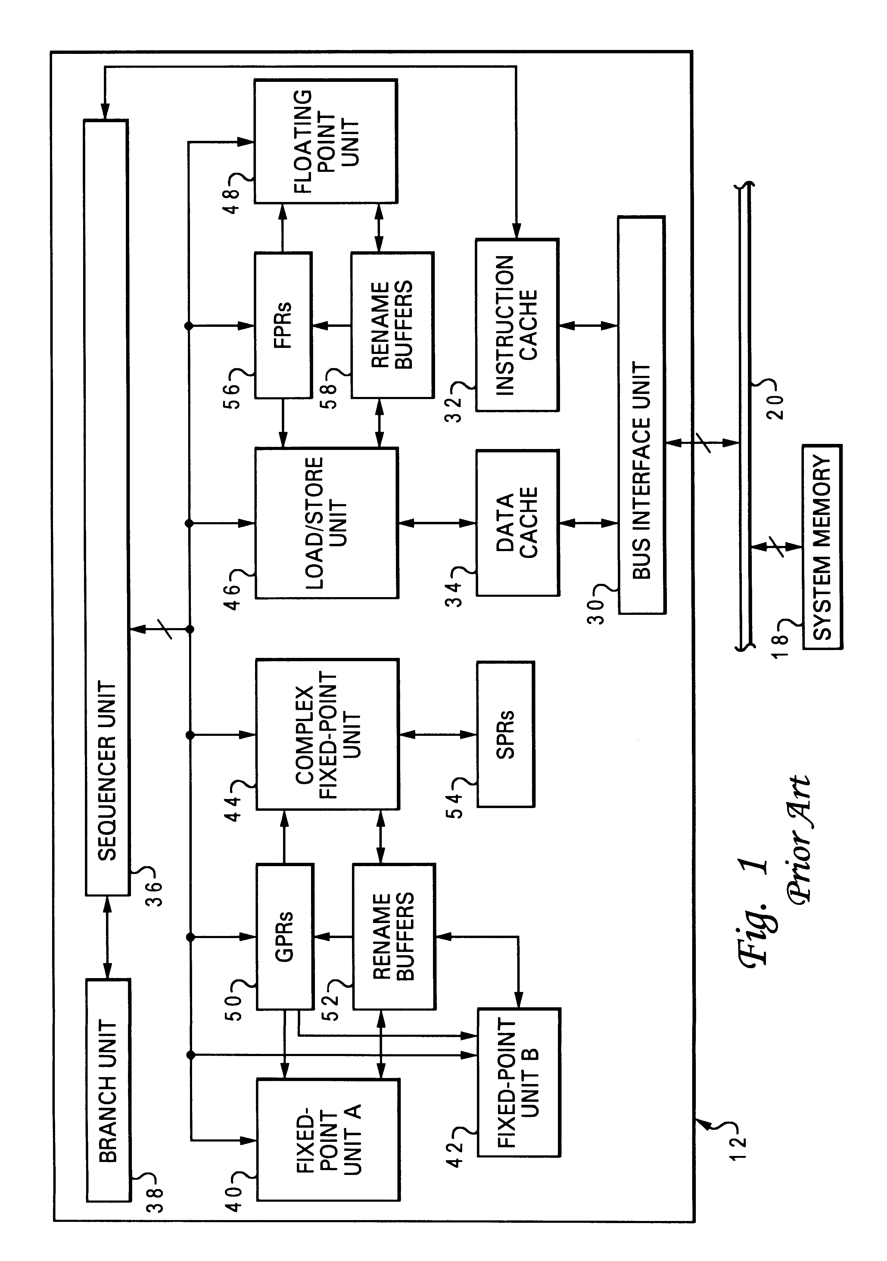
Furthermore, programmers often use the same registers as temporary storage registers rather than moving data to and from system memory (since the latter process takes a large amount of time relative to processor speed), so a small register set can cause a "bottleneck" in the performance stream.
One problem with conventional processing is that operations are often delayed as they must be issued or completed using queues or buffers.
The load queue severely limits the number of outstanding loads that can be pending in the system.
If the load queue is already full and another cache miss occurs, the processor core stalls until an entry in the queue becomes available.
Several other processing delays are associated with the operation of, or interaction with, the caches, particularly the L1 cache.
These types of delays can also arise with operations whose targets are other than register renames, such as instruction fetch units, or translation tables requesting addresses.
Caches can also be "write-through," but this leads to increased demands on bus bandwidth.
Cache coherency protocols introduce further complexities and requirements into the interaction of the caches.

Method used


Image

  • Layered local cache with lower level cache updating upper and lower level cache directories
  • Layered local cache with lower level cache updating upper and lower level cache directories
  • Layered local cache with lower level cache updating upper and lower level cache directories

Examples


Embodiment Construction

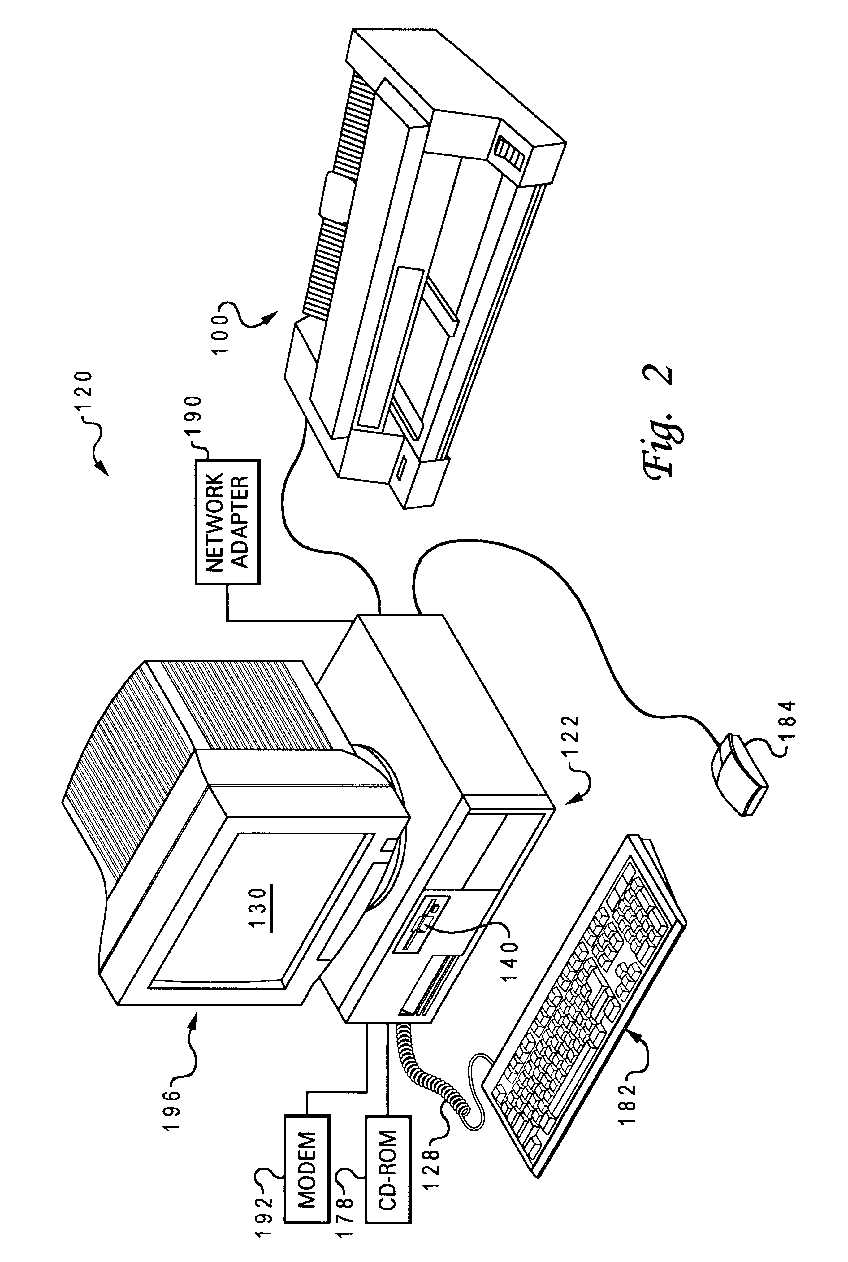
With reference now to the figures, and in particular with reference to FIG. 2, a data processing system 120 is shown in which the present invention can be practiced. The data processing system 120 includes processor 122, keyboard 182, and display 196. Keyboard 182 is coupled to processor 122 by a cable 128. Display 196 includes display screen 130, which may be implemented using a cathode ray tube (CRT), a liquid crystal display (LCD), an electrode luminescent panel or the like. The data processing system 120 also includes pointing device 184, which may be implemented using a track ball, a joy stick, touch sensitive tablet or screen, track path, or as illustrated a mouse. The pointing device 184 may be used to move a pointer or cursor on display screen 130. Processor 122 may also be coupled to one or more peripheral devices such a modem 192, CD-ROM 178, network adapter 190, and floppy disk drive 140, each of which may be internal or external to the enclosure or processor 122. An outp...


PUM


Abstract

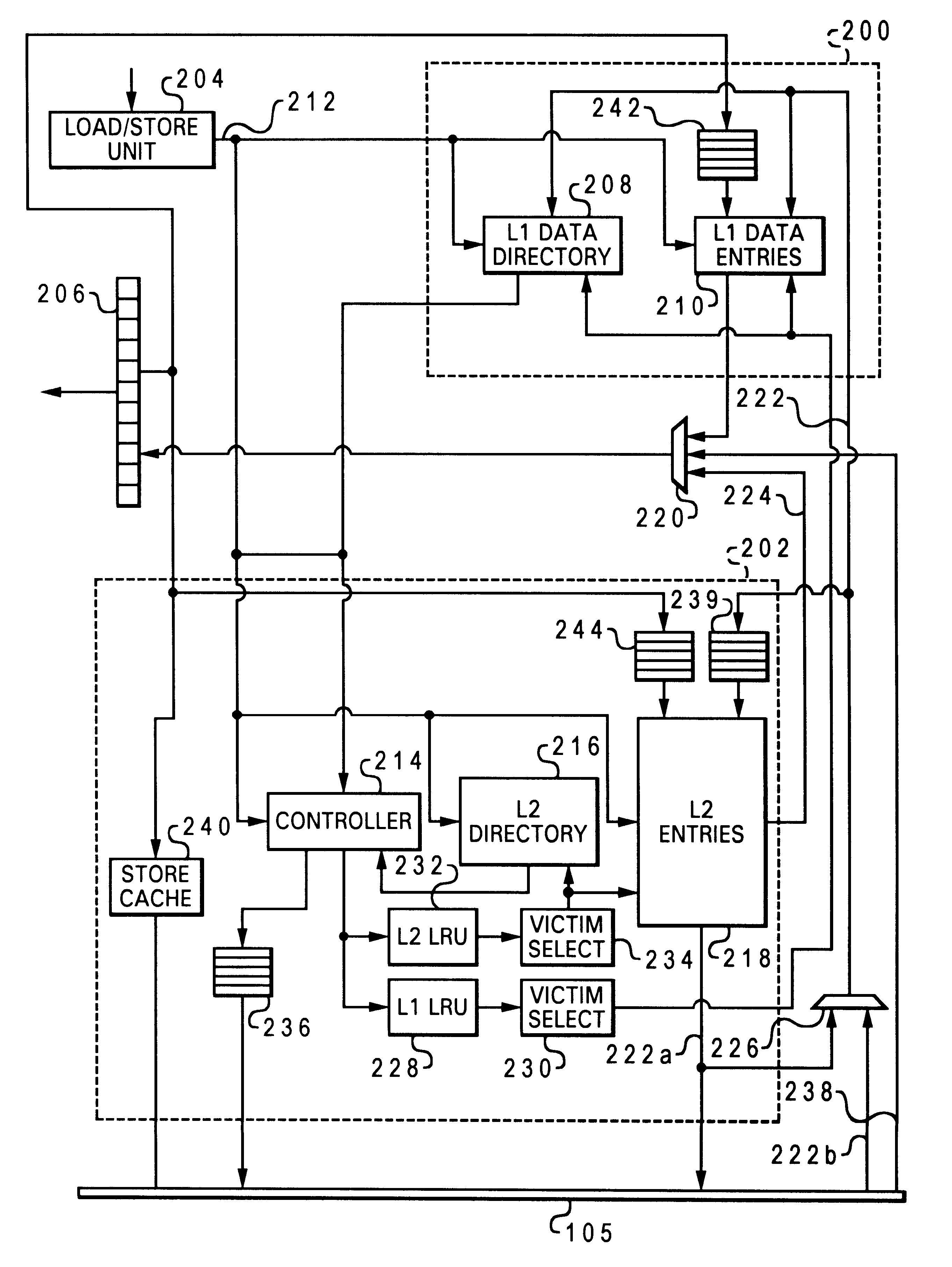
A method of improving memory access for a computer system, by sending load requests to a lower level storage subsystem along with associated information pertaining to intended use of the requested information by the requesting processor, without using a high level load queue. Returning the requested information to the processor along with the associated use information allows the information to be placed immediately without using reload buffers. A register load bus separate from the cache load bus (and having a smaller granularity) is used to return the information. An upper level (L1) cache may then be imprecisely reloaded (the upper level cache can also be imprecisely reloaded with store instructions). The lower level (L2) cache can monitor L1 and L2 cache activity, which can be used to select a victim cache block in the L1 cache (based on the additional L2 information), or to select a victim cache block in the L2 cache (based on the additional L1 information). L2 control of the L1 directory also allows certain snoop requests to be resolved without waiting for L1 acknowledgement. The invention can be applied to, e.g., instruction, operand data and translation caches.

Description

1. Field of the InventionThe present invention generally relates to computer systems, and more specifically to an improved method of accessing memory values (operand data or instructions) used by a processor of a computer system. In particular, the present invention makes more efficient use of a multi-level cache hierarchy, and ports values directly to, e.g., a rename register, instruction buffer, or translation table of the processor without the need for load queues or reload buffers in high level caches.2. Description of Related ArtThe basic structure of a conventional computer system includes one or more processing units connected to various input / output devices for the user interface (such as a display monitor, keyboard and graphical pointing device), a permanent memory device (such as a hard disk, or a floppy diskette) for storing the computer's operating system and user programs, and a temporary memory device (such as random access memory or RAM) that is used by the processor(...

Claims


Application Information

Patent Timeline
IPC IPC(8): G06F12/08G06F12/10
CPCG06F12/0811G06F12/0897G06F12/0831G06F12/1027
Inventor ARIMILLI, RAVI KUMARCLARK, LEO JAMESDODSON, JOHN STEVENGUTHRIE, GUY LYNN
Owner IBM CORP
Learn More