Internal heat exchanger accumulator

Inactive Publication Date: 2002-10-15
HALLA CLIMATE CONTROL CANADA
View PDF50 Cites 107 Cited by
  • Summary
  • Abstract
  • Description
  • Claims
  • Application Information

AI Technical Summary

Problems solved by technology

At low heat loads it is not desirable or possible to evaporate all the liquid.
However, liquid refrigerant entering the compressor (known as "flooding") causes system efficiency loss and can cause damage to the compressor.
Some refrigerant systems are more susceptible to moisture ingression and damage than others, especially less modern systems.
This is an added expense and is only used when required to reduce flooding.
This liquid refrigerant returning to the compressor reduces system efficiency.
The prior art recognizes that a conventional heat exchanger can be used as an IHX (U.S. Pat. No. 5,562,157, U.S. Pat. No. 5,609,03

Method used


Image

  • Internal heat exchanger accumulator
  • Internal heat exchanger accumulator
  • Internal heat exchanger accumulator

Examples


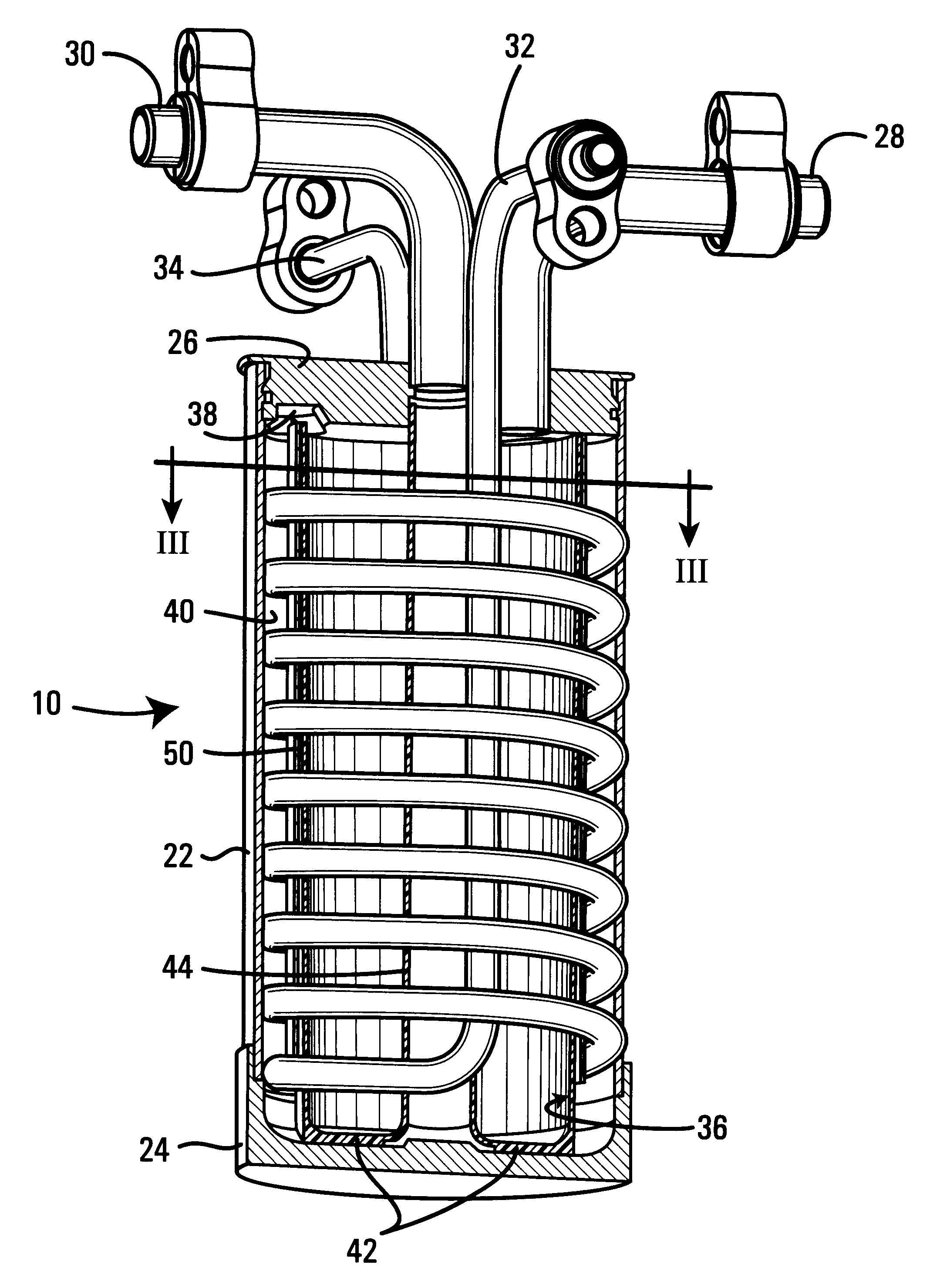
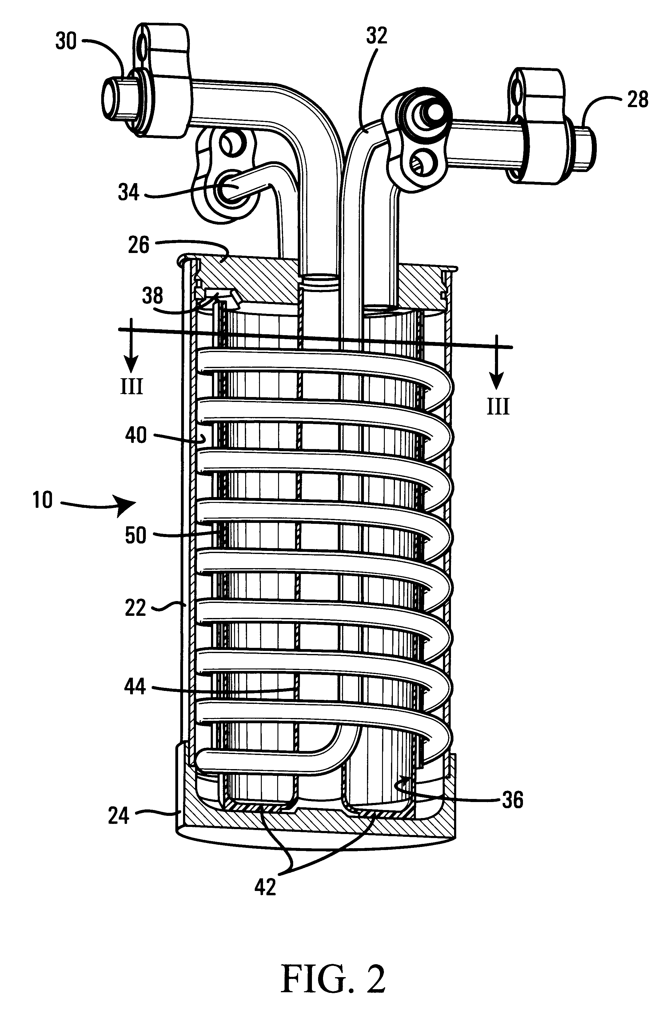
Embodiment Construction

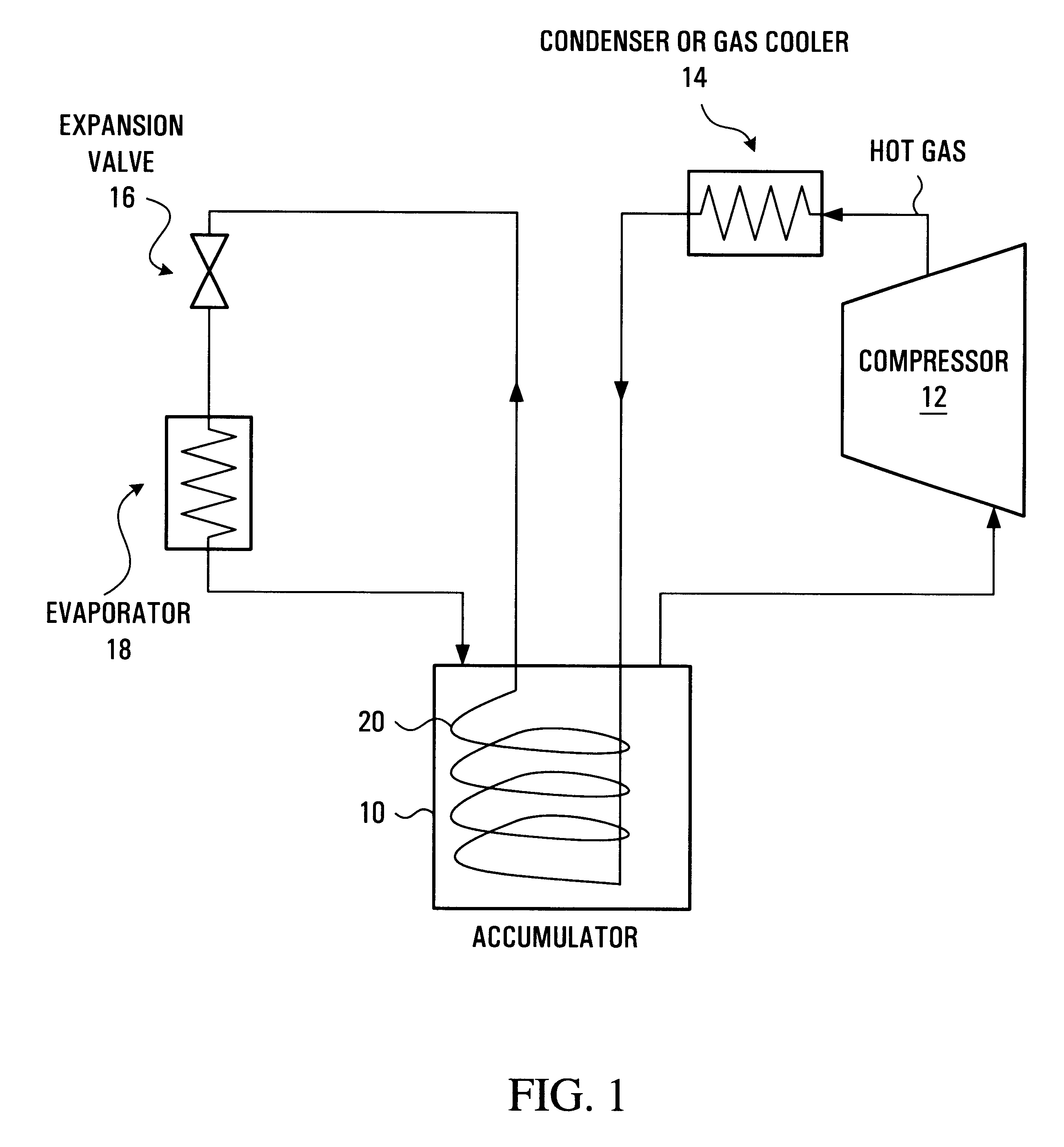
The circuit diagram of FIG. 1 shows a schematic closed circuit air-conditioning system which may be used as a cooling unit or as a heat pump. Refrigerant fluid is stored in liquid form in an accumulator 10 to be drawn therefrom in gaseous form to the inlet of a compressor 12. The compressor delivers hot high-pressure refrigerant gas to a condenser 14 where the gas is cooled and typically partially converted to a liquid form. Refrigerant fluid from the condenser (still under high pressure) is expanded to a lower pressure through an expander valve 16, thereby undergoing a rapid drop in temperature, the low pressure cold fluid being heated in an evaporator 18 from where it is returned to the accumulator 10 in a mixed flow of liquid and gas. Depending upon the loading of the system more or less of the refrigerant fluid is condensed and evaporated, refrigerant that is in excess of the instantaneous requirements of the system being stored in liquid form in the accumulator 10. As thus far ...


PUM

PropertyMeasurementUnit
Lengthaaaaaaaaaa
Pressureaaaaaaaaaa
Flow rateaaaaaaaaaa

Abstract

An accumulator for an air-conditioning (refrigeration or heat pump) system is designed to reduce flooding due to greater effective internal volume while at the same time incorporating an internal heat exchanger for better system performance, and providing better evaporation and controlled thermal properties. The accumulator embodies an outer housing that co-axially surrounds an inner liner. The inlet directs the refrigerant into the inner volume formed by the liner, wherein the liquid refrigerant and compressor oil are contained and insulated from the wall of the outer housing. A heat exchanger is arranged in the annular space between the outer housing and the inner liner and circulates a flow of condensate therethrough before delivering it to the expansion device. In this way the condensate is cooled for higher performance and at the same time refrigerant passing out of the accumulator is vaporized more completely.

Description

a) Field of the InventionThe present invention relates to improvements of an accumulator for use in an air-conditioning or heat pump system, and more particularly to a suction accumulator suitable for use in an air-conditioning system of a motor vehicle.b) Description of the Prior ArtClosed-loop refrigeration / heat pump systems conventionally employ a compressor that is meant to draw in gaseous refrigerant at relatively low pressure and discharge hot refrigerant at relatively high pressure. The hot refrigerant condenses into liquid as it is cooled in a condenser. A small orifice or valve divides the system into high and low-pressure sides. The liquid on the high-pressure side passes through the orifice or valve and turns into a gas in the evaporator as it picks up heat. At low heat loads it is not desirable or possible to evaporate all the liquid. However, liquid refrigerant entering the compressor (known as "flooding") causes system efficiency loss and can cause damage to the compre...

Claims


Application Information

Patent Timeline
IPC IPC(8): F25B40/00F25B43/00F28D7/02B60H1/32
CPCF25B40/00F25B43/006F28D7/024F25B2309/061Y10T29/49394F25B2400/051F25B2400/03
Inventor DICKSON, TIMOTHY R.WHITTLE, WAYNESTOBBART, MICHELLE M.
Owner HALLA CLIMATE CONTROL CANADA
Why Eureka
Try Eureka