
Pipe having replaceable wear resistant lined coupler

a technology of wear-resistant pipe and coupler, which is applied in the direction of hose connection, siphon, bend, etc., can solve the problems that ceramic casting technology limits the cost effective commercial use of ceramic materials, and achieve the effects of superior wear-resistant construction and configuration, superior wear-resistant pipe structure, and rapid and cost-effective formation of pipe structur

Inactive Publication Date: 2002-10-22
CONSTR FORMS
View PDF27 Cites 58 Cited by
  • Summary
  • Abstract
  • Description
  • Claims
  • Application Information

AI Technical Summary

Benefits of technology

The present invention is particularly directed to a superior wear resistant pipe structure for carrying of high abrasive materials and particularly to an end insert of a superior wear-resistant construction and configuration and to the method of application. Generally, in accordance with the present invention, a special hard wear-resistant insert liner is formed of a special hardened material, such as a special carbide material, a special ceramic material or the like. The hard wear-resistant end insert liner is secured within a recessed end of the pipe and particularly in an end coupler section or member. The insert liner is, in one aspect of this invention, adhesively bonded in place and subject to release using heat or other operative energy field to soften or otherwise effectively release the adhesive and permit ready removal of the insert liner as well as the adhesive. This solution provides not only a rapid and cost effective formation of the pipe structure with the necessary wear resistant characteristic but permits quick inexpensive replacement of the insert liner.
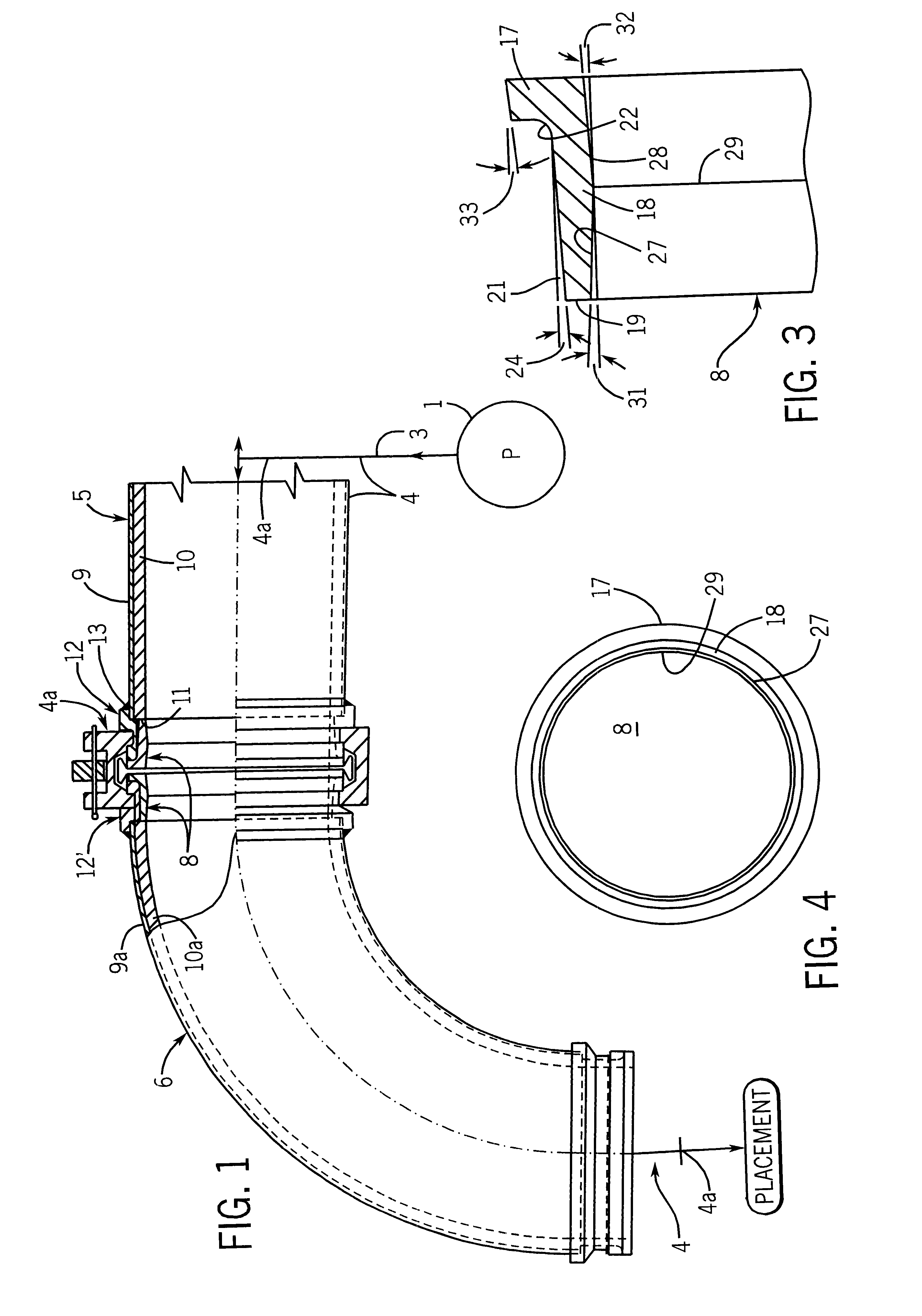
The insert liner is generally formed as an L-shaped member having an outer flange adapted to abut the end of the body member of the coupler and an inwardly projecting tubular portion or member extended beneath the coupler and into abutting engagement with the end of the pipe. The outer diameter of the insert liner is tapered inwardly to define a slight but a distinct gap, which gap preferably increases from an outer portion of the tubular portion to the abutting pipe end. This increases the available space for the epoxy and provides optimum bonding characteristic, and allows easy insertion and removal. This feature further provides an improved casting characteristic. The leading edge or flange provides additional wear resistant material at the location of primary wear characteristics and also provides a mechanical interlock which will prevent the liner from dislodging and plugging the system in the event of excessive insert liner wear before replacement. The flange also minimizes casting time and requirements, creating a more round condition due to its configuration. The flange areas also permits the use of a puller or hammer to aid in removal of the insert liner, as well as providing a relatively strong outer wall so the insert liner can be tapped in with a hammer without breakage.
The present liner is equally applicable to any pipe section carrying highly abrasive materials including straight pipe sections, elbow sections, reducing sections and the like, and provides both a highly cost effective insert and additionally contributes to the useful operating life of the piping sections as a result of the convenient and relatively inexpensive field replacement.

Problems solved by technology

The present limitations on the ceramic casting technology limits the cost effective commercial usage of ceramic materials.

Method used


Image

  • Pipe having replaceable wear resistant lined coupler
  • Pipe having replaceable wear resistant lined coupler
  • Pipe having replaceable wear resistant lined coupler

Examples


Embodiment Construction

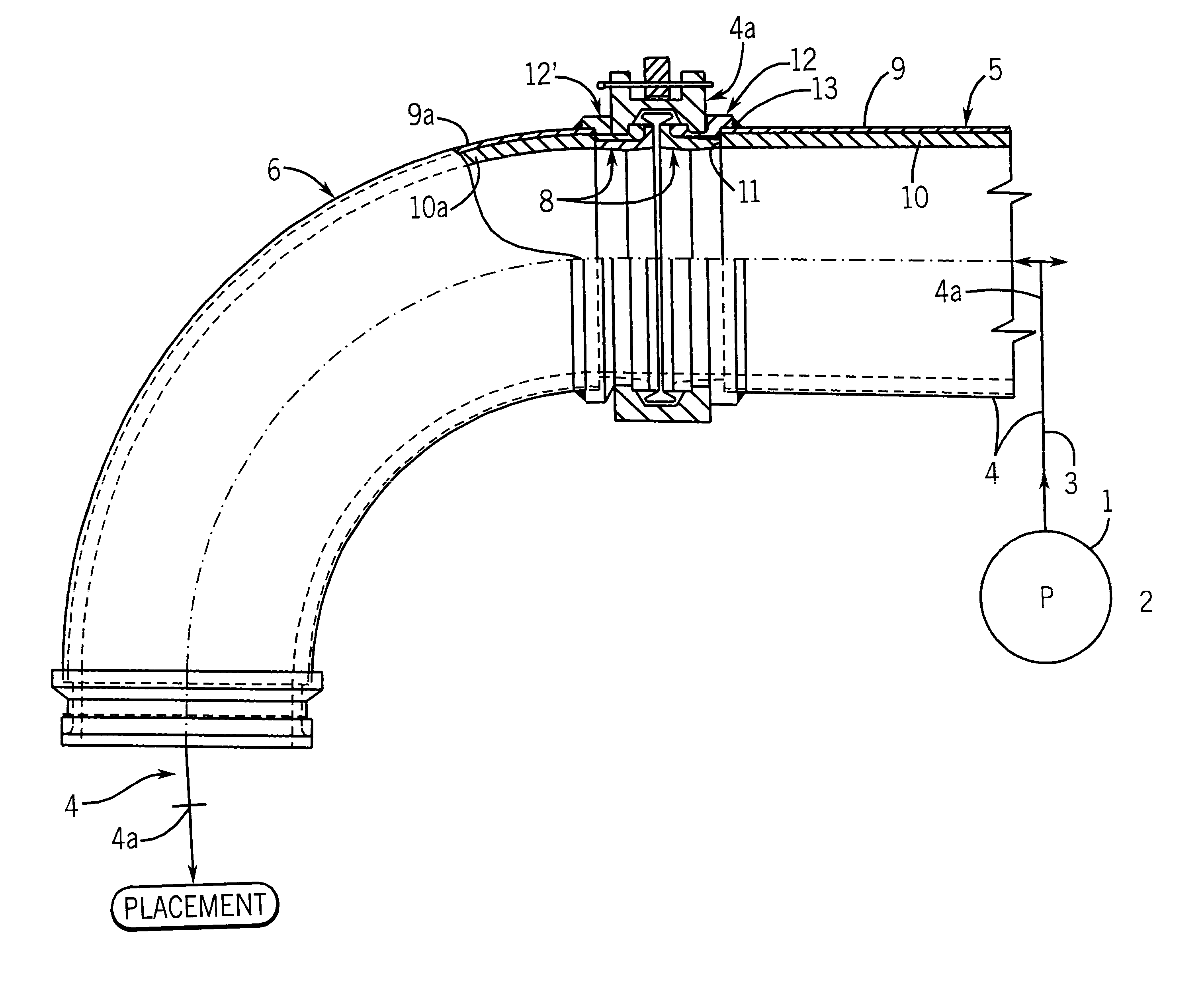
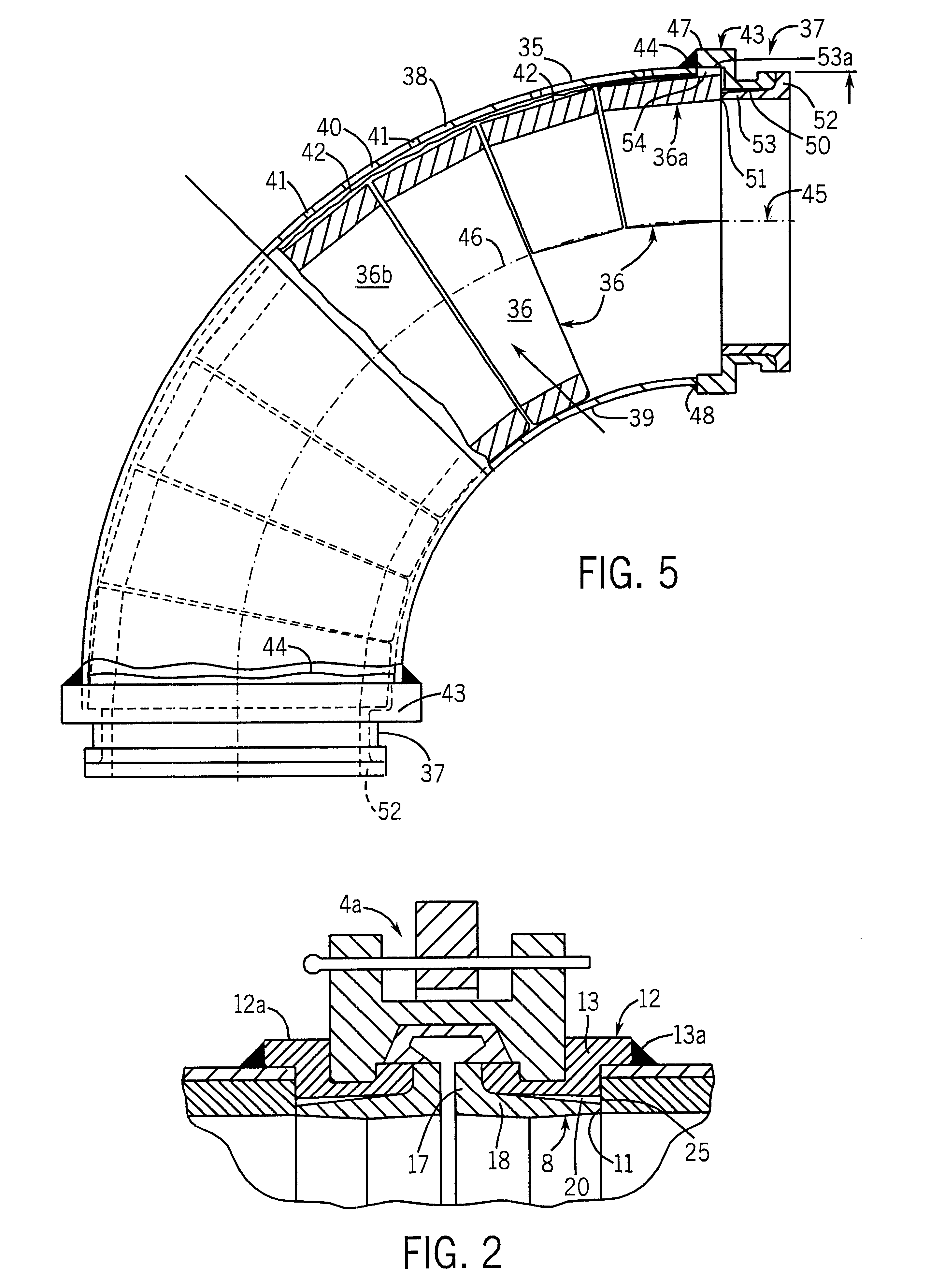
Referring to FIG. 1, a diagrammatic illustration of a concrete pumping system is illustrated incorporating pipe sections constructed in accordance with the present invention and for purposes of illustration and description of the preferred embodiments of the present invention. In FIG. 1, a concrete pump 1 has a high pressure outlet for establishing concrete flow under a relatively high pressure for transport from a central location to one or more in placement locations. The flowline 3 connects the pump outlet to placement locations 3a in accordance with known constructions. The flowline 3 consists of a plurality of individual pipe sections 4 which are connected to each other in line-by suitable releasable couplings 4a. In FIG. 1, a straight pipe 5 and an elbow pipe 6 are illustrated in detail interconnected to each other by a coupling 4a. The pipe 5 and the elbow 6 with the interconnecting portion are more fully illustrated in FIGS. 2-4, with the coupling 4a including special end in...


PUM

PropertyMeasurementUnit
Fractionaaaaaaaaaa
Fractionaaaaaaaaaa
Fractionaaaaaaaaaa

Abstract

A pipe section for concrete includes an end coupler interconnecting to another pipe section in a flow line. The coupler has an outer clamp secured extended from the pipe end with a coupling groove. An encircling clamp has sides located in the grooves of adjacent pipe sections to lock the pipe section together. The body and pipe end form an inner recess extending from the pipe end. An insert liner has a tubular portion matching the recess, with the outer surface of the tubular portion tapered to form a gap within the recess. The insert liner has an outer flange matching the outer diameter of the body and abuts the body. The inner wall of the liner has a central transition point from which the wall tapers inwardly in opposite directions to the outer end. The body member is formed of a high strength ductile steel. The insert liner is formed of a wear resistant material having a Rockwell hardness of 80 to 90. A carbide alloy consisting essentially of carbides, martensite, bainite and austenite, and 12-15% chromium, 2-3% carbon and traces nickel, molybdenum and austenite. A toughened ceramic is disclosed. The liner is adhesively bonded to the body using an epoxy adhesive which is responsive to heat for release of the liner. The liner is inserted by applying adhesive on the tubular portion and then pushing the liner into the recess.

Description

This invention relates to a pipe having a replaceable wear resistant lined coupler and particularly to such pipe for carrying abrasive and wear creating materials, in particular, concrete.Concrete pumping is used in placement of concrete in various applications. The present invention has been particularly applied to the concrete pumping technology but is equally applicable to other transport of highly abrasive material through a piping system. In concrete pumping as well as other abrasive material transport, excessive wear of the pipe is a common problem, and a special problem at the coupling of pipe sections, particularly where there is a change of flow direction.In concrete pumping systems, initial pipe sections are interconnected to each other with releasable couplings. A typical system is disclosed in U.S. Pat. No. 3,705,737, which issued December, 1972 and U.S. Pat. No. 4,305,607 which issued Dec. 15, 1981, to the assignee of this invention. The couplings of the pipes generally...

Claims


Application Information

Patent Timeline
IPC IPC(8): E04G21/04F16L57/06F16L57/00F16L43/00F16L23/00F16L23/12
CPCE04G21/04F16L23/125F16L43/00F16L57/06
Inventor KLEMM, ROBERT E.LEHNHARDT, GARY D.
Owner CONSTR FORMS
Learn More