Radio unit casing including a high-gain antenna

a radio unit and antenna technology, applied in the direction of individual energised antenna arrays, substation equipment, transmission, etc., can solve the problems of large angle between the beam direction pointing at the satellite and the aperture normal of the antenna unit, and the integration of an antenna uni

Inactive Publication Date: 2002-10-22
HIGHBRIDGE PRINCIPAL STRATEGIES LLC AS COLLATERAL AGENT
View PDF37 Cites 53 Cited by
  • Summary
  • Abstract
  • Description
  • Claims
  • Application Information

AI Technical Summary

Benefits of technology

Another object of the present invention is to provide a radio unit casing with an integrated antenna that has a nearly constant gain in the whole scan range and the ability to search for and to track individual satellites.
Other advantages are that the beams of the antenna unit avoids to be scattered by the user and that the antenna unit in the radio casing has no movable or protruding parts.

Problems solved by technology

The satellites can reach portable radio units in areas where cellular communication is unavailable due to the lack of necessary cellular towers, base stations or compatible standards.
One problem is the integration of an antenna unit with transmit and receiving means in a casing where the area of the antenna unit has to be limited to the geometrical dimensions of the portable radio unit.
Another problem is to obtain a high antenna directivity in spite of the limited area available on a radio unit casing of a portable radio unit.
A further problem occurs when the portable radio unit is moved or turned in such a way that the angle between the beam direction pointing at the satellite and the aperture normal of the antenna unit becomes large.
Yet another problem occurs when the antenna in the portable radio unit has to scan a wide portion of the upper hemisphere to locate satellites.
A similar problem is that the antenna in the portable radio unit has to track the satellite with its transmit and receiving beams during movement of the satellite and / or the portable radio unit.
Another problem occurs when radio waves between the satellite and the portable radio unit are weak due to low output power from the satellite or the portable radio unit, or there is an attenuation in the radio wave propagation path between the satellites and the radio unit antenna.
Yet another problem is to avoid that the beam of the antenna unit is scattered by the user of the portable radio unit.

Method used


Image

  • Radio unit casing including a high-gain antenna
  • Radio unit casing including a high-gain antenna
  • Radio unit casing including a high-gain antenna

Examples


first embodiment

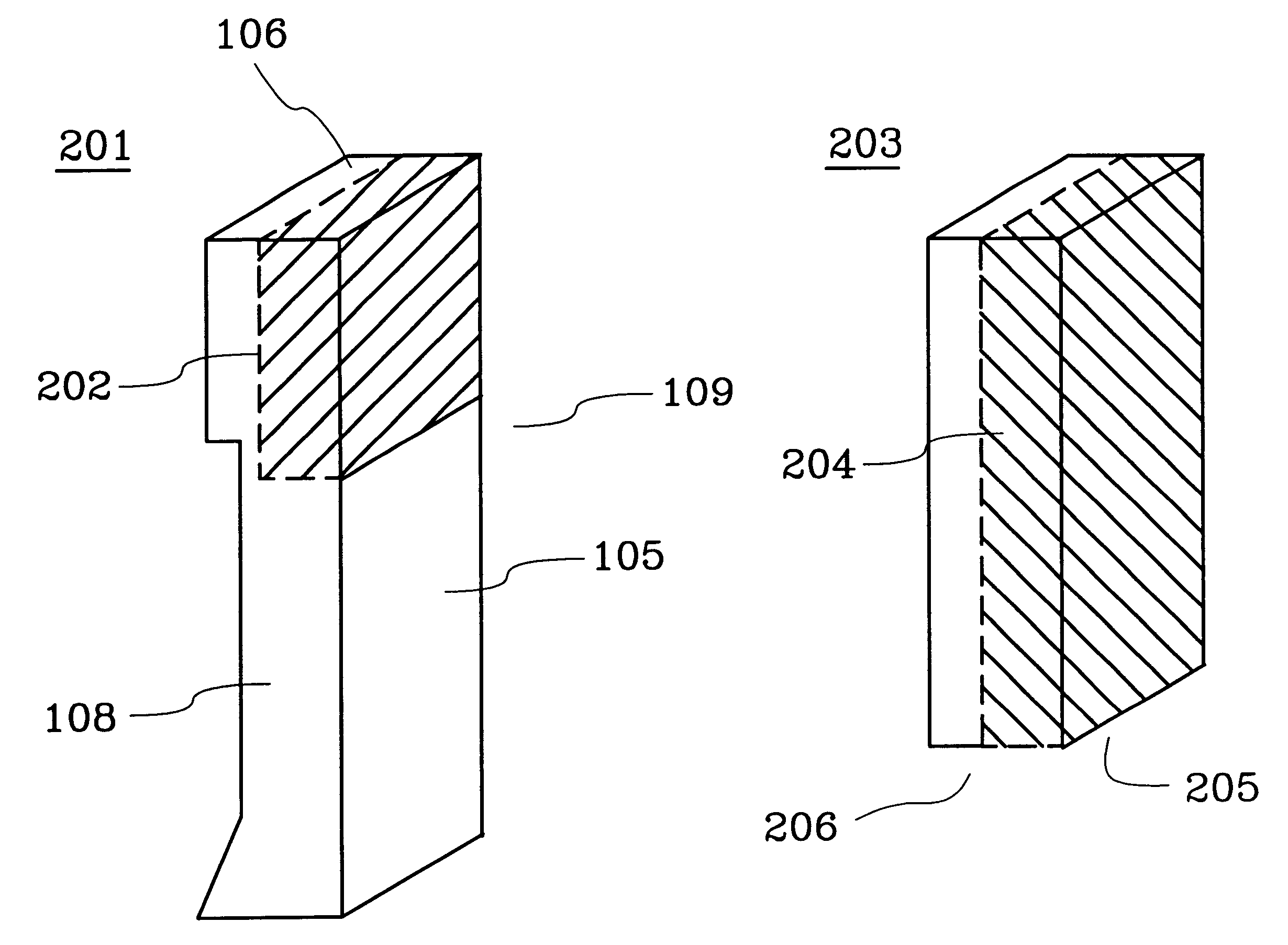
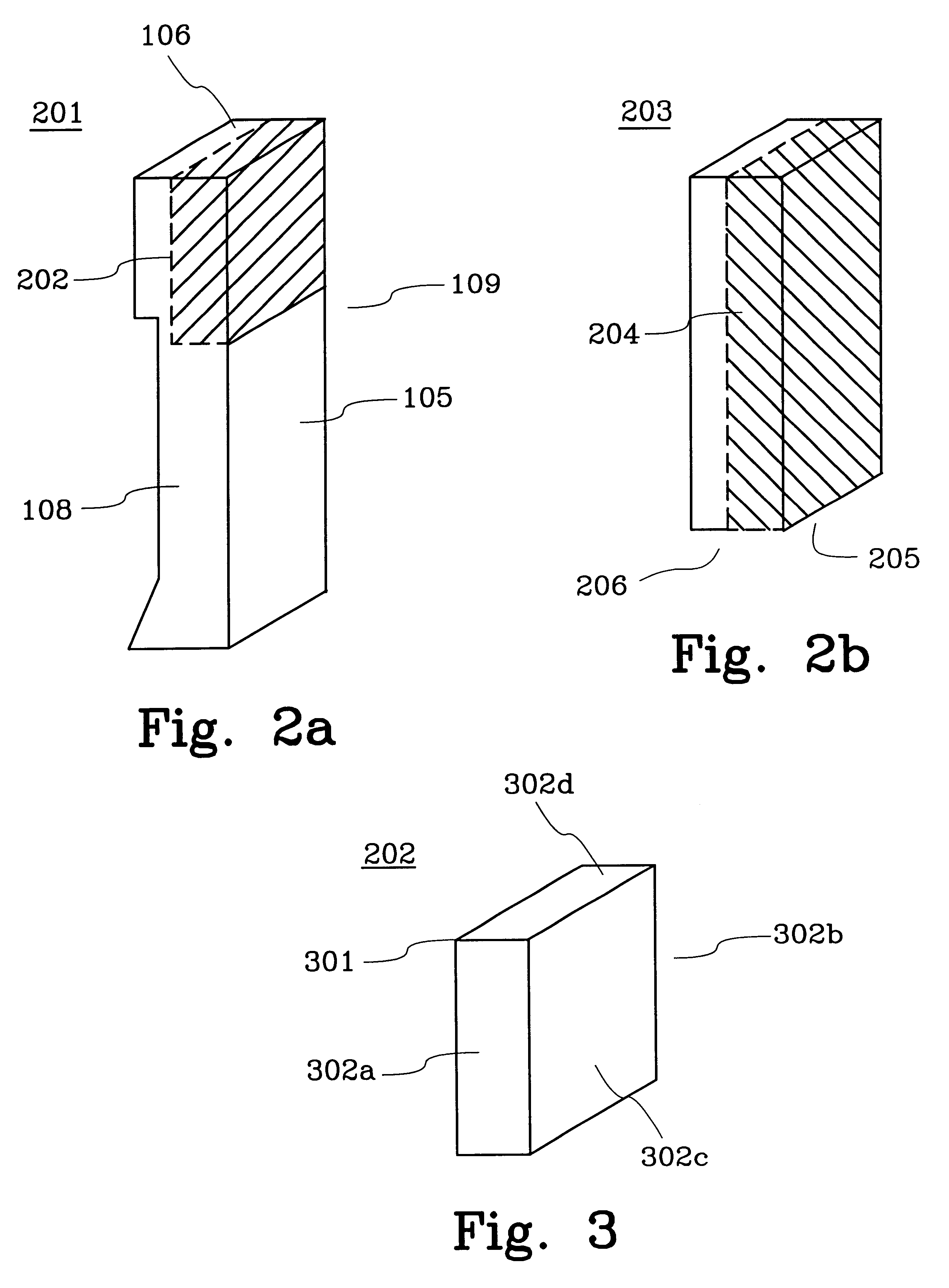
FIG. 2a is a perspective view of a first example of a radio unit casing 201 with a satellite antenna unit 202 according to the present invention. The satellite antenna unit 202 is integrated in the upper part of the radio unit casing 201 which is illustrated in FIG. 2a by the dashed areas of the radio unit casing 201.

The upper part of the radio unit casing 201 is the area which is close to the top surface 106 of the radio unit casing 201.

FIG. 2b is a perspective view of a second example of a first embodiment of a radio unit casing 203, e.g. a transceiver casing, with a satellite antenna unit 204 according to the present invention. The satellite antenna unit 204 is integrated in a major part of the radio unit casing 203 which is illustrated in FIG. 2b by the dashed areas of the radio unit casing 203.

FIG. 3 illustrates the antenna unit 202 according to FIG. 2a. The antenna unit 202 comprises an antenna array 301 (phased array) with transmission and reception means which can electrical...

second embodiment

FIG. 4b is a perspective view of a second example of a radio unit casing 403, e.g. a transceiver casing, with a satellite antenna unit 404 according to the present invention. The satellite antenna unit 404 is integrated in a major part of the radio unit casing 403 which is illustrated in FIG. 4b by the dashed areas of the radio unit casing 403.

FIG. 5 illustrates the antenna unit 402 according to FIG. 4a. The antenna unit 401 comprises an antenna array 501 which can electrically steer its radio beams by using known techniques. The antenna array 501 comprises transmission and reception means on a number of adjacent and co-operating antenna array surfaces 502 arranged like a part of an ellipsoid to be conformaly integrated in the partly ellipsoid shaped upper part of the radio unit casing 401. This entails that the antenna array 501 faces in a multitude of directions which gives the antenna unit a wide scan volume. Each one of the antenna array surfaces 502 can as an example have a fir...


PUM


Abstract

A radio unit casing (401) for a portable radio unit with an integrated antenna array capable of operating in a satellite communication mode. The antenna array comprises a number of adjacent co-operating antenna array surfaces arranged to be conformaly integrated in the radio unit casing (401). The antenna array surfaces faces in a multitude of directions which gives the antenna array a wide scan volume. The surfaces of the antenna array comprise a number of interleaved transmit and receive antenna elements, e.g. circular formed patches, in multiplayer structure.

Description

The present invention relates to a radio unit casing for a portable radio unit with a single high-gain antenna unit for transmitting and receiving radio signals within a wide scan range in a satellite communication system.DESCRIPTION OF RELATED ARTThe name portable radio unit includes all portable equipment intended for radio communication, like mobile phones, transceivers, pagers, telex, electronic notebooks and communicators. These equipments can be used in any type of radio communication system, such as cellular networks, satellite or small local networks.One type of radio communication is cellular mobile communication where portable radio units communicate with each other or with fixed units through mobile basestations on the ground. Portable radio units, for example mobile phones, which typically transmit and receive signals at a frequency of approximately 900 Megahertz or 1800-1900 Megahertz (MHz), are well known.Recently it has become important for another type of radio commu...

Claims


Application Information

Patent Timeline
Patent Type & Authority Patents(United States)
IPC IPC(8): H01Q1/24H01Q5/00H01Q21/06
CPCH01Q1/243H01Q5/42H01Q21/065
Inventor SCHEFTE, HENRYDERNERYD, SVEN ANDERS GOSTAREINEFJORD, JAN STAFFAN
Owner HIGHBRIDGE PRINCIPAL STRATEGIES LLC AS COLLATERAL AGENT
Why Eureka
Try Eureka