Liquid fuel rocket engine with a closed flow cycle

a liquid fuel rocket engine and closed flow technology, which is applied in the direction of rocket engine plants, machines/engines, jet propulsion plants, etc., can solve the problems of unavoidable impulse losses, adversely affecting the thrust power complex and expensive construction, so as to reduce the impulse losses of the rocket engine, increase the pressure in the main liquid fuel flow, and reduce the impulse loss

Inactive Publication Date: 2002-10-29
ASTRIUM GMBH
View PDF2 Cites 29 Cited by
  • Summary
  • Abstract
  • Description
  • Claims
  • Application Information

AI Technical Summary

Benefits of technology

to provide a liquid fuel rocket engine with a closed flow cycle which nevertheless has a simplified construction while maintaining the advantages of the closed flow cycle;
The condensation of the exhaust gas from the gas generator in the main fuel flow can be further facilitated by reducing the temperature of the exhaust gas prior to the introduction of the exhaust gas into the main fuel flow. For this purpose, for example, a heat exchanger is arranged for cooperation with the exhaust gas duct for cooling the exhaust gas of the gas generator. Such a heat exchanger may for example be provided in the form of a thermal contact between the exhaust gas duct and the main fuel flow line. For example, the exhaust gas duct may be provided in the form of a coil with a number of turns around the main fuel flow line whereby the respective thermal contact is provided between the exhaust duct and the main fuel supply line. The cool main fuel flow thereby reduces the temperature of the gas generator exhaust gas. Another possibility for reducing the temperature of the gas generator exhaust gases is achieved by mixing a portion of the main fuel flow with the exhaust gas with the aid of a further bypass fuel line or fuel branch line which feeds cool fuel from the main line into the exhaust gas duct or ducts. The exhaust gases of the gas generator are thus cooled before they are introduced into the main fuel flow by the mixing with a certain proportion of the cool main fuel whereby the temperature of the exhaust gases can be notably lowered and a condensation of the exhaust gas at the introduction of the exhaust gas, that follows the mixing, into the main fuel flow is facilitated.

Problems solved by technology

However, open cycle engines have a separate discharge for the exhaust gases of the gas generator whereby impulse losses are unavoidable.
Such impulse losses adversely affect the thrust power of the rocket engine.
Rocket engines with a closed flow cycle avoid such impulse losses, however closed flow cycle engines have the disadvantage that a complicated and expensive construction is required particularly of the interface between the main flow supply lines and the combustion chamber.
The structural components in the interface must all be constructed with due regard to the configuration, size and position of all other components of the interface area which makes the construction and design involved and hence expensive.

Method used


Image

  • Liquid fuel rocket engine with a closed flow cycle
  • Liquid fuel rocket engine with a closed flow cycle
  • Liquid fuel rocket engine with a closed flow cycle

Examples


Embodiment Construction

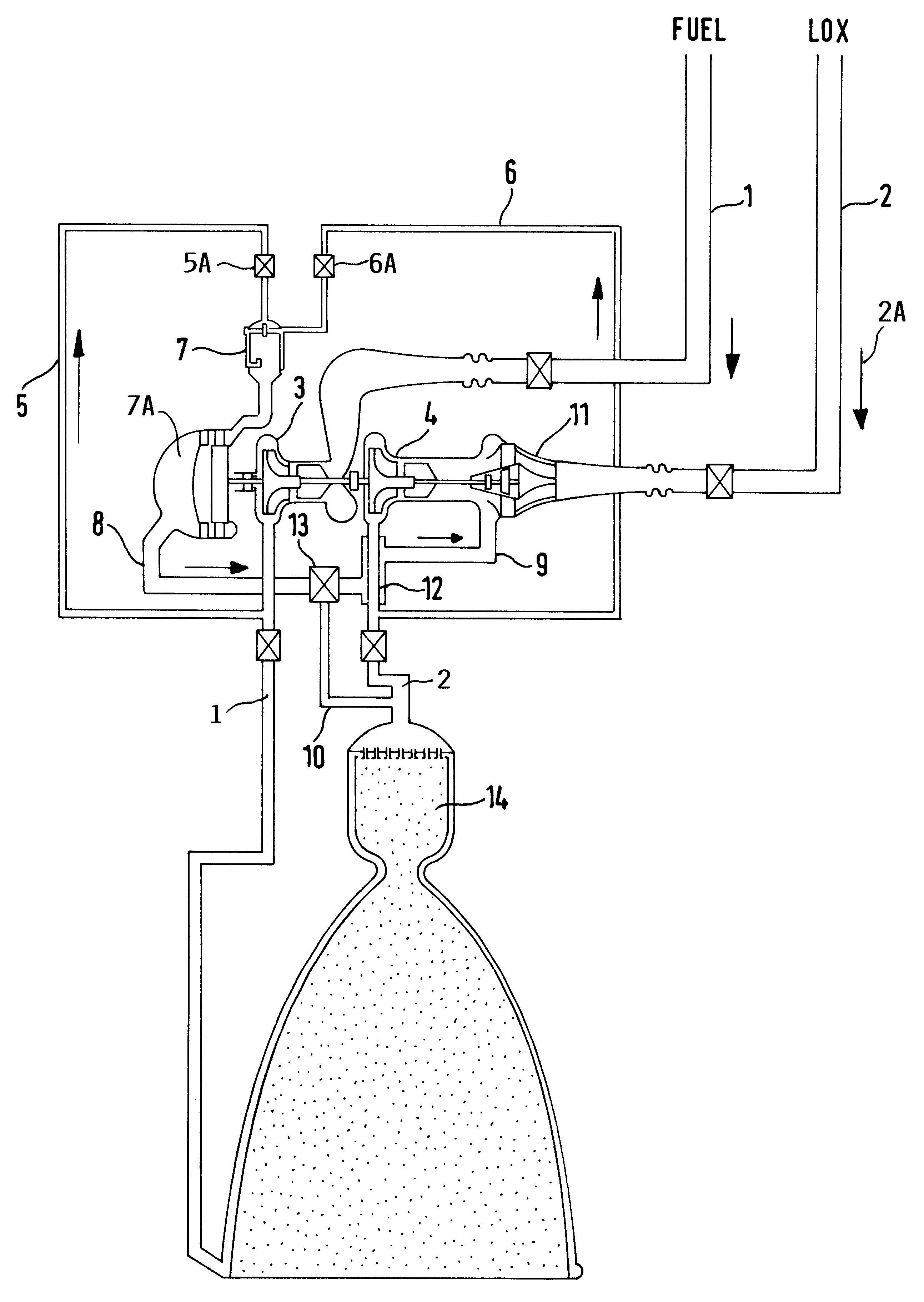
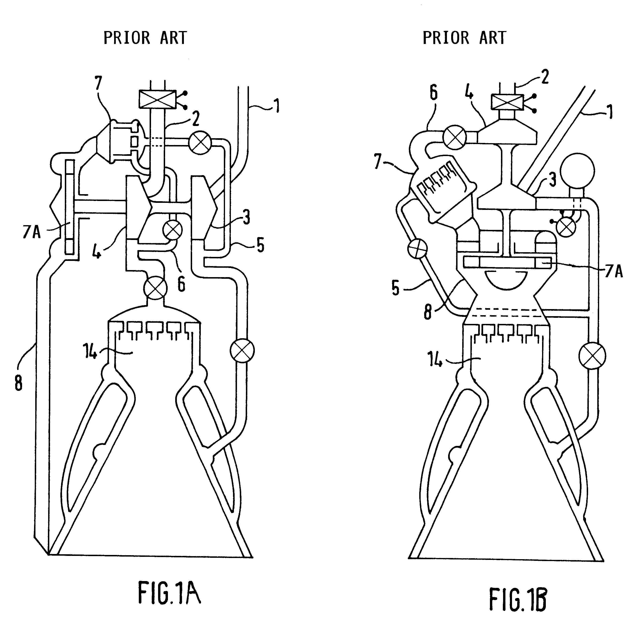
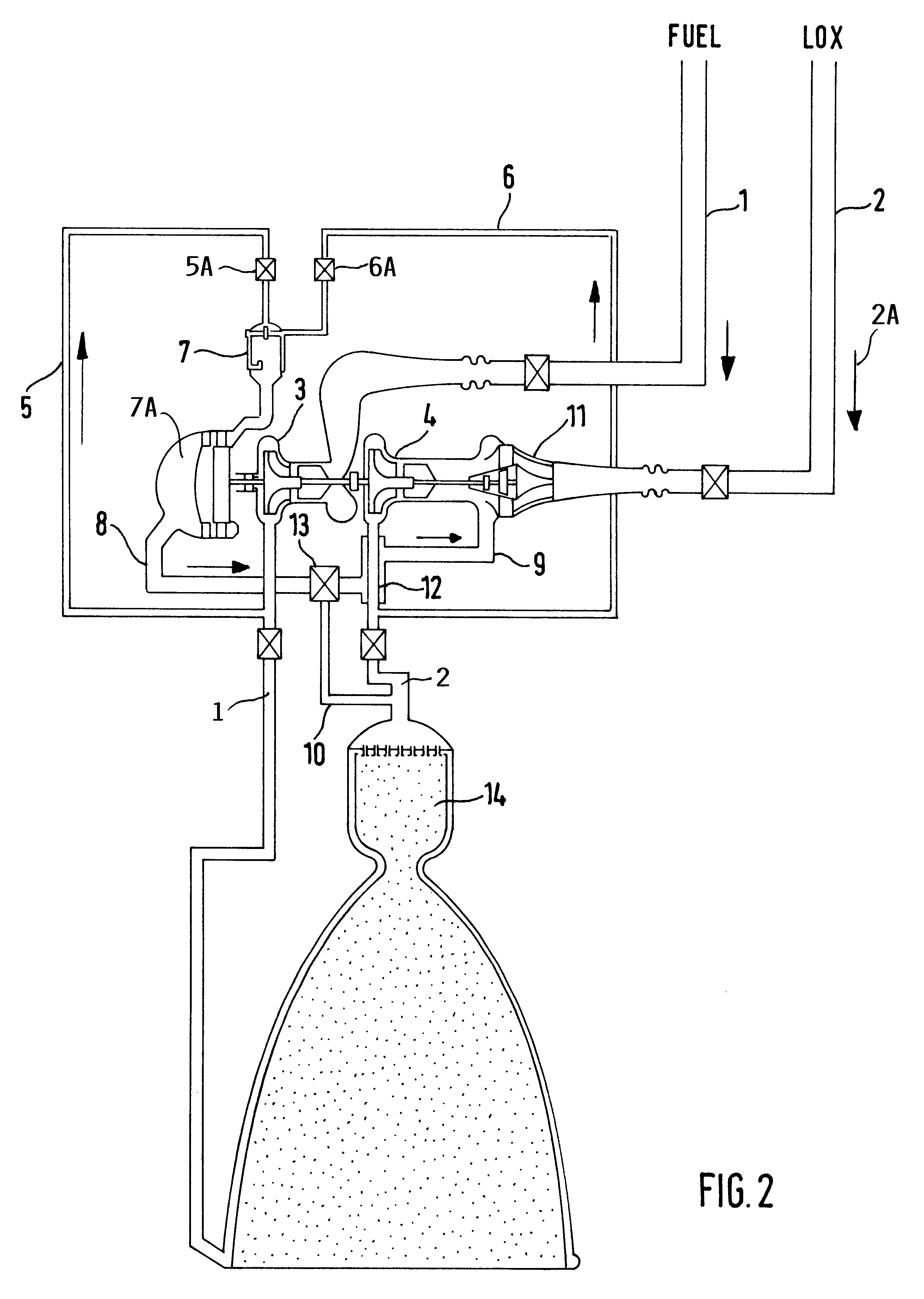
FIGS. 1A and 1B show conventional liquid fuel rocket engines wherein FIG. 1A shows a rocket engine with an open flow cycle while FIG. 1B shows a closed flow cycle engine.

In FIG. 1A the fuel and oxygen supply lines 1, 2 feed the main flow of liquid fuel to a combustion chamber 14. Turbo pumps 3, 4 are arranged in the fuel and oxygen supply lines 1, 2, respectively. More specifically, the turbo pump 3 is arranged in the fuel line 1 for feeding a liquid combustible fuel. The turbo pump 4 is arranged in the oxygen supply line 2 for supplying liquid oxygen as a fuel component. These turbo pumps 3 and 4 increase the pressure of the liquid fuel and oxygen before it enters into the combustion chamber 14. An auxiliary or bypass fuel flow line 5 leads from a junction point downstream of the pump 3 to a gas generator 7. Similarly, an auxiliary bypass oxygen line 6 leads from a point downstream of. the pump 4 to the gas generator 7 for fueling the gas generator 7 which drives the turbo pumps 3,...


PUM


Abstract

A liquid fuel rocket engine with a closed direct auxiliary flow cycle has a combustion chamber connected to each liquid fuel source through a respective main liquid fuel supply line. A turbo pump is provided in each main fuel supply line. The turbo pump is driven by a gas generator which is connected to a first bypass fuel supply line for supplying fuel to the gas generator. An exhaust gas duct (8, 9, 10) leads from the gas generator into at least one main fuel supply line for feeding gas generator exhaust gas into the main fuel supply line upstream of the turbo pump.

Description

This application is based on and claims the priority under 35 U.S.C. .sctn.119 of German Patent Application 199 58 310.2, filed on Dec. 3, 1999, the entire disclosure of which is incorporated herein by reference.The invention relates to a liquid flow rocket engine with a closed flow cycle. Such an engine is equipped with at least one main liquid flow supply line for each fuel component including fuel and oxygen components. The supply line or lines are connected to the combustion chamber. A turbo pump it provided in each liquid fuel component supply line.BACKGROUND INFORMATIONLiquid fuel rocket engines of the type described above are normally equipped with a gas generator for driving the turbo pump or pumps in the fuel component supply lines. The gas generator is connected to at least one bypass fuel line to provide fuel for operating the gas generator. The exhaust gases from the exhaust gas generator are fed through a respective exhaust gas duct back into the main fuel supply line o...

Claims


Application Information

Patent Timeline
Patent Type & Authority Patents(United States)
IPC IPC(8): F02K9/48F02K9/00
CPCF02K9/48
Inventor MAEDING, CHRIS UDO
Owner ASTRIUM GMBH
Why Eureka
Try Eureka