Modular belt with tapered oblong hinge pins

a technology of hinge pins and modules, applied in conveyors, packaging, transportation and packaging, etc., can solve the problems of large differences in pull strength on straight lines, difficult molding of apertures, waste of belt strength to accommodate turns, etc., to avoid other shortcomings, avoid waste of belt strength, and avoid molding difficulties

Inactive Publication Date: 2002-11-05
HARTNESS INT INC +1
View PDF10 Cites 57 Cited by
  • Summary
  • Abstract
  • Description
  • Claims
  • Application Information

AI Technical Summary

Benefits of technology

Wasted belt strength, large differences in pull strength on straights and turns, complex provided designs, molding difficulties, and other shortcomings are avoided by the invention, which provides a modular conveyor belt capable of following straight or curved paths. The belt is constructed of a succession of rows of belt modules having hinge elements projecting from each end and spaced apart along the width of the row. The forward hinge elements of a row are interleaved with the rearward hinge elements of an adjacent row. Openings in the interleaved hinge elements are generally aligned to form a passageway across the width of the rows to accommodate, preferably, a tapered oblong hinge pin, which forms a hinge between adjacent rows.

Problems solved by technology

The requirement of following a curved path causes problems not found in straight-running belts.
Thus, belt strength must be wasted to accommodate turns.
The patent also discloses the use of tapered shaft apertures to help share tensile loads, but such apertures are difficult to mold.
Thus, turns must be long and gradual, taking up otherwise usable space.
Smaller turning ratios are generally limited by interference between the interleaved link ends as they collapse at the inside of a turn.

Method used


Image

  • Modular belt with tapered oblong hinge pins
  • Modular belt with tapered oblong hinge pins
  • Modular belt with tapered oblong hinge pins

Examples


Embodiment Construction

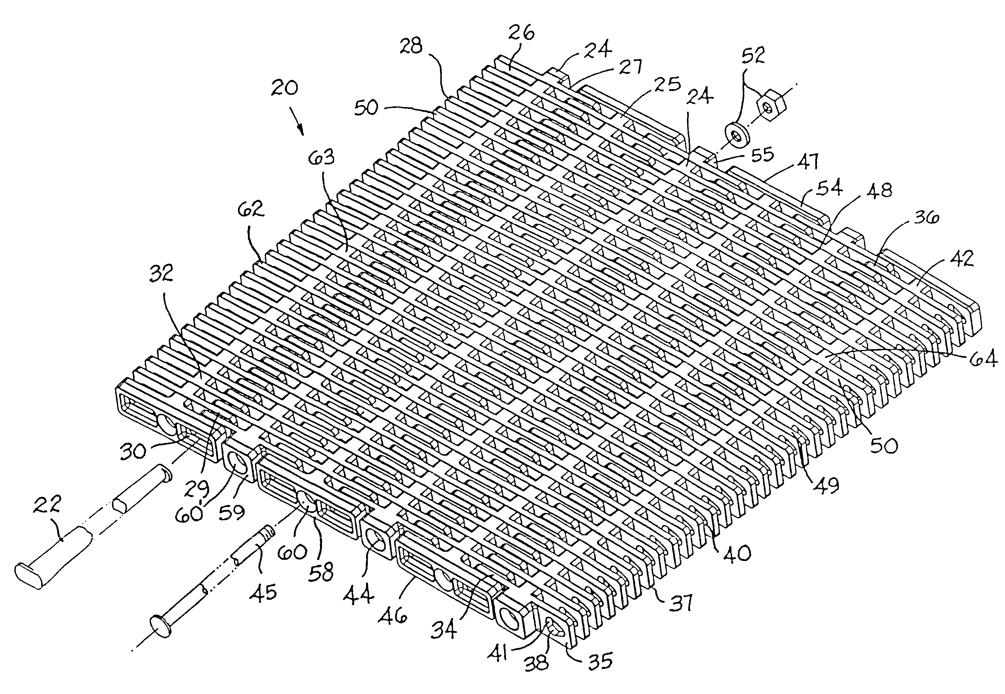
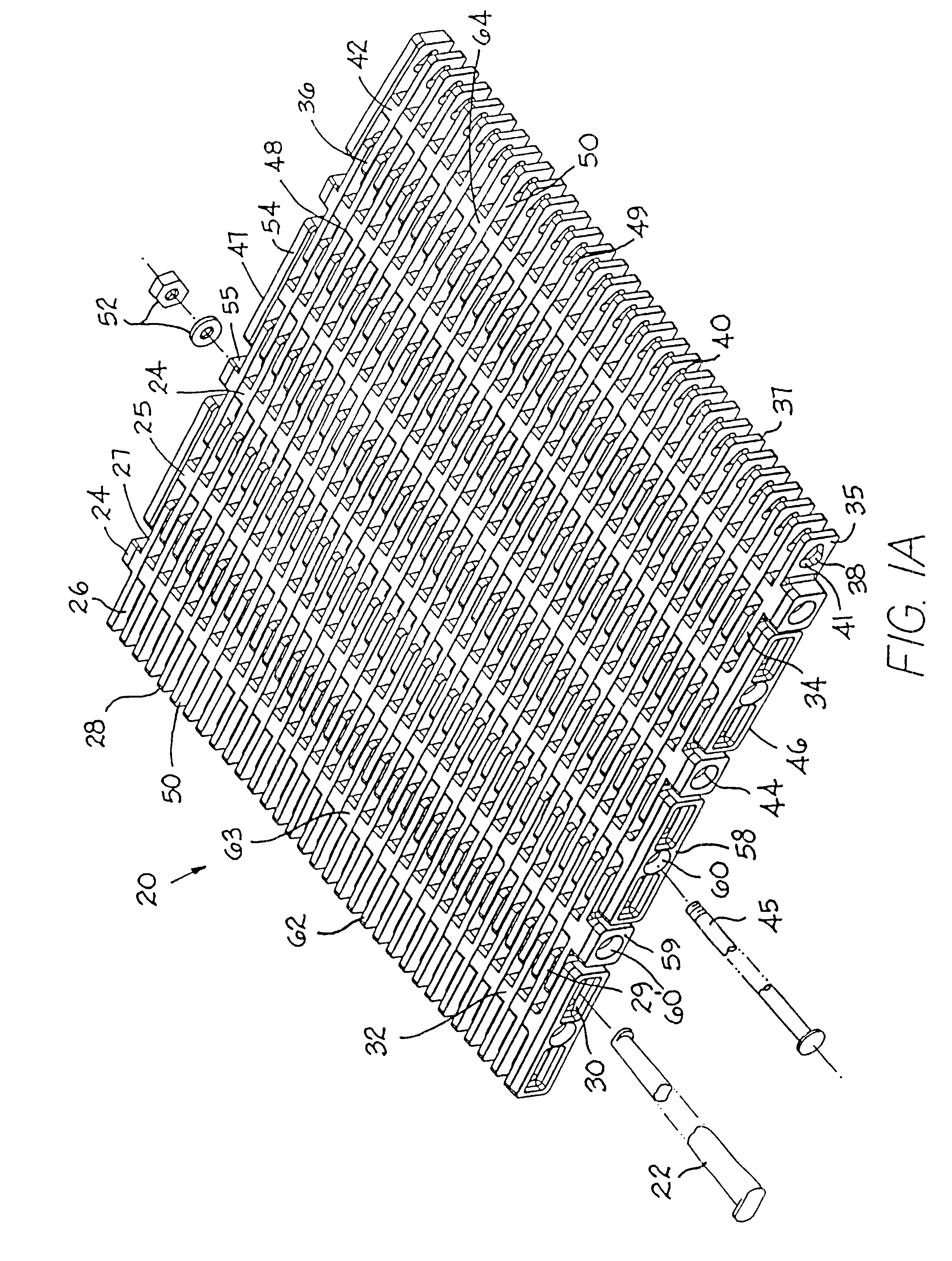
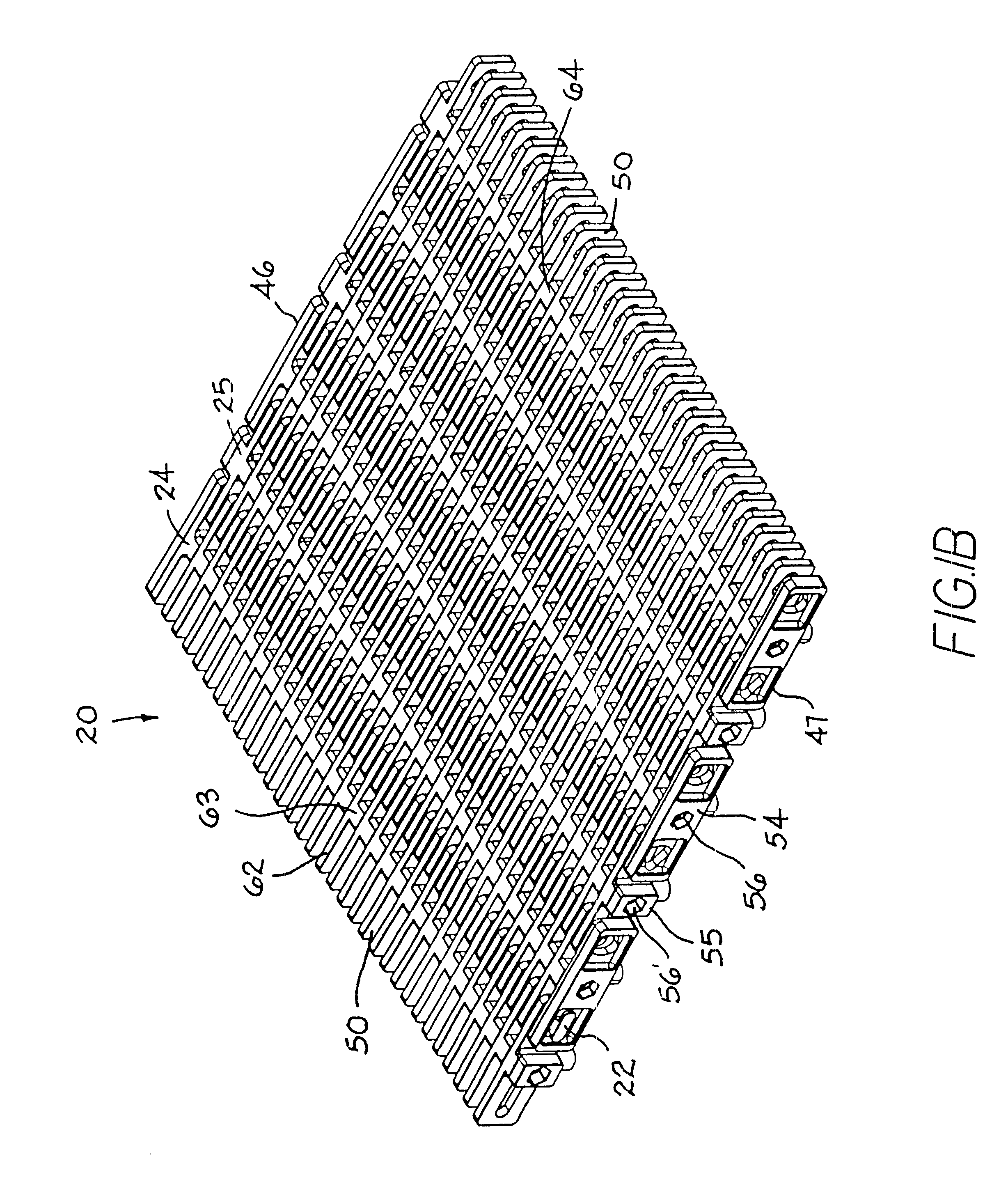
Portions of an exemplary version of a radius belt 20 having features of the invention are shown negotiating a turn in FIG. 1A and a straight in FIG. 1B. The endless belt is composed of a succession of belt rows, preferably made of injection-molded plastic, connected end to end by pivot rods, or hinge pins 22. In the version shown, there are two styles of belt rows: a first row 24 and a second row 25. The first row comprises a first set 26 of hinge elements along a first end 28 of the row and a second set 27 of hinge elements along an opposite second end 29 of the row. An elongated slot 30 is formed in each of the first and second hinge elements of the first row. The slots at each end are axially aligned across the width of the belt and are elongated in the direction of belt travel. The first and second sets of hinge elements extend from a central portion 32 forming a transverse connecting member across the width of the row. The second row 25 comprises a first set 34 of hinge element...


PUM


Abstract

A modular conveyor belt (20) constructed of a series of rows (24, 25) of belt modules hingedly interlined by tapered oblong hinge pins (22) and suitable for following straight or curved conveyor paths. Aligned slots (30) formed in one set of hinge elements between successive rows are elongated in the direction of belt travel to allow the belt to fan out in turns. Fan-shaped apertures (38) formed in interleaved hinge elements of an adjacent row and aligned axially with the slots to admit a hinge pin (22) allow the belt to pivot at the hinge to articulate about a sprocket (181) or idler (186) or to enter and exit an incline. The oblong hinge pin has a first region at a first end (88) with a constant long axis to share the belt load among hinge elements encompassing the first region on straight runs. A second region of the hinge pin at an opposite second end (89) has a tapered oblong cross section, the long axis of which increases with distance from the second end to define a variable pitch and to spread the belt tension among the hinge elements at the outside of a turn encompassing the second region. Each belt row can be constructed of individual links stacked together on a support element (45) and retained by fasteners (52) or of integrally molded modules each comprising a transverse connecting member from which leading and trailing hinge elements extend. Accessory attachments, such as teeth (160) or sideguards (150), can be added to the belt. The belt can be driven by a cog, a roller chain, or other driving means driving lugs (172) extending from the bottom of the belt. The drive surfaces of the lugs can be obliquely arranged for better load sharing.

Description

The invention relates to conveyor belts and, more particularly, to modular plastic conveyor belts constructed of plastic belt modules hingedly interlinked by tapered oblong hinge pins.Because they do not corrode and are easy to clean, plastic conveyor belts are used widely, especially to convey food products. Modular plastic conveyor belts are made up of molded plastic modular links, or belt modules, arranged in rows. Spaced apart link ends extending from each end of the modules include aligned apertures to accommodate a pivot rod. The link ends along one end of a row of modules are interleaved with the link ends of an adjacent row. A pivot rod, or hinge pin, journalled in the aligned apertures of the end-to-end-connected rows, connects adjacent rows together to form a two-ended belt or an endless conveyor belt capable of articulating about a drive sprocket.In many industrial applications, conveyor belts are used to carry products along paths including curved, as well as straight, s...

Claims


Application Information

Patent Timeline
Patent Type & Authority Patents(United States)
IPC IPC(8): B65G17/08B65G17/06
CPCB65G17/08B65G17/086B65G2201/02B65G2207/12B65G2207/30
Inventor HORTON, PAUL L.BOGLE, DAVID W.HAWKINS, JR., JOHN C.HARTNESS, III, WILLIAM R.DAVIDSON, MARK W.
Owner HARTNESS INT INC
Why Eureka
Try Eureka