Six-degree of freedom micro-positioner

a micro-positioner and freedom technology, applied in the direction of mechanical control devices, ignition automatic control, instruments, etc., can solve the problems of requiring substantial worker time, affecting the quality of the finished product, so as to achieve the effect of fine precision object manipulation

Inactive Publication Date: 2002-11-26
GOVERNMENT OF THE US REPRESENTED BY THE SEC OF COMMERCE THE
View PDF4 Cites 39 Cited by
  • Summary
  • Abstract
  • Description
  • Claims
  • Application Information

AI Technical Summary

Benefits of technology

One object of the present invention is to provide an improved technique for fine precision object manipulation in manufacturing and assembly processes.

Problems solved by technology

However, if there is a misalignment of the fiber ends, this process can take as long as forty-five minutes to an hour.
Conventional assembly of opto-electronic devices can, as discussed above, require substantial worker time and therefore be quite costly.
Positioning devices currently available do not provide the precision and range of motion required in these and other technological fields.
However, the resulting movement in each of the X and Y directions is not purely linear.
Rather, the proposed structure introduces a yaw which is unacceptable for precision manufacturing applications.
Known prior art positioning devices can not eliminate rotational cross talk unless additional actuators are included in the device to apply counterbalancing rotation and thereby ensure pure linear movement.
These actuators add undesirable complexity and costs to the devices.
Additionally, complex control algorithms must be developed and used to operate multiple actuators in concert to compensate for the cross talk.
In the proposed micro-positioning stage discussed above, as well as other proposed stages, the rotational cross talk error is inherent in the design.
That is, applying a force intended to move a stage in one direction necessarily produces an unintended rotation.
Conventional deformable structure micro-positioners use sensors which are typically located at a position which results in inaccurate measurement of the true stage displacement.
For example, when a force is applied to an epoxy connection between the actuator and the moving stage, the epoxy compresses, resulting in up to a 60 percent loss in applied force.
Using an epoxy or screws for the coupling, it is also difficult to obtain a pure parallel alignment of the actuator and the moving stage.
Unparallel alignment results in a loss of force in the system.
Furthermore, misalignment between the components may produce damaging stresses on the actuator.
Epoxy couplings are also subject to maintenance difficulties and durability limits.
This cutting and cleaning process may damage both the actuator and the deformable structure micro-positioner.
Conventional deformable structure micro-positioners can be subjected to forces which may damage the individual components of a positioner.
However, a practical adaptation of macro-scale Stewart platforms to the micro-scale using a deformable structure platform has not been previously achieved.
However, actuators of the type typically used in micro-scale positioners do not have the required range of motion necessary for use in the struts of a micro-scale adapted Stewart platform.
Hence, more expensive and much larger actuators must be used in the proposed micro-scale Stewart platforms.
Each of these drives are subject to sticktion and backlash.
Hence, this manipulator is not capable of achieving fine movement, since none of the actuator configurations usable in this device can produce movement without some sticktion and / or backlash.
The conventional process for manufacturing deformable structure micro-positioning devices is costly and time-consuming.

Method used


Image

  • Six-degree of freedom micro-positioner
  • Six-degree of freedom micro-positioner
  • Six-degree of freedom micro-positioner

Examples


Embodiment Construction

One-Degree of Freedom embodiment:

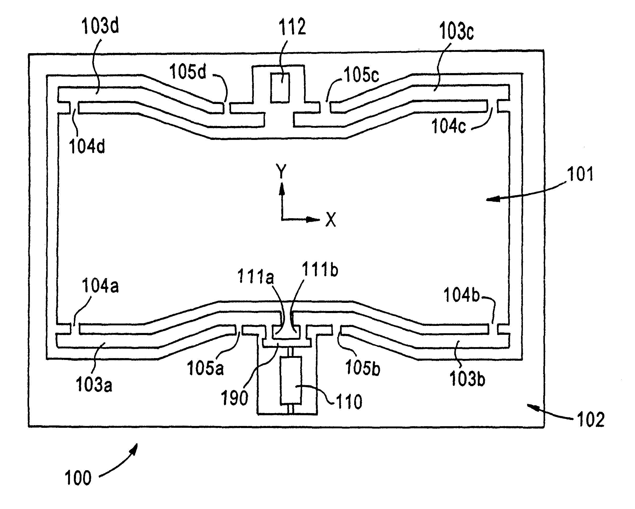
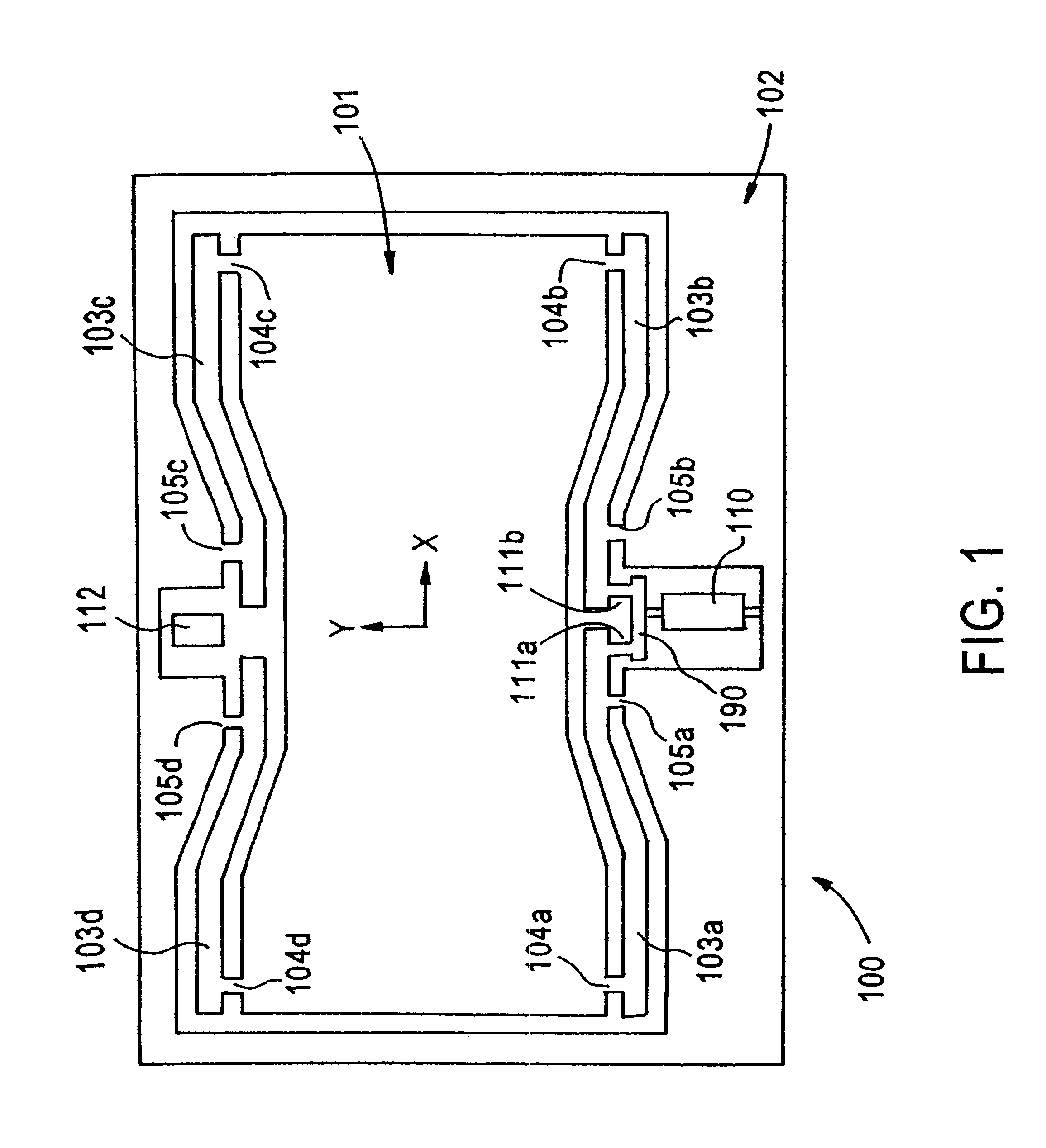
FIG. 1 depicts a view of a high performance, low fabrication cost deformable structure parallel cantilever biaxial micro-positioning stage 100 in accordance with one aspect of the present invention. The deformable structure micro-positioner includes a moving stage 101 formed within and planar to a support structure 102. The moving stage is connected to the support structure via four levers 103a, 103b, 103c and 103d. Lever 103a is attached to the moving stage via flexure 104a and to the support structure via flexure 105a. Lever 103b is attached to the moving stage via flexure 104b and to the support structure via flexure 105b. Lever 103c is attached to the moving stage via flexure 104c and to the support structure via flexure 105c. Lever 103d is attached to the moving stage via flexure 104d and to the support structure via flexure 105d.

The four levers are bi-axially symmetrical. Lever pair 103a and 103d is symmetrical to lever pair 103b and 103c with ...


PUM


Abstract

A positioning device is provided. The positioning device includes a movable platform and a monolithic base. Struts are attached to both the movable platform and the monolithic base. The monolithic base moves each of the attached struts to cause the movable platform to move.

Description

The present invention relates to positioners for positioning objects, and more particularly to a deformable positioning stage.Assembly of optic-electronic devices requires precision alignment of optical fibers with lasers or sensors and then bonding. A worker looking through a microscope at the end of a fiber conventionally executes this precision alignment and bonding process.The alignment and bonding process can take as little as five minutes. However, if there is a misalignment of the fiber ends, this process can take as long as forty-five minutes to an hour. Misalignment often occurs because the fibers are subject to other than pure linear movement during the alignment process. Accordingly, a need exists for an improved alignment process which will reduce, if not eliminate, misalignment of a fiber end.It is likely that in the next ten years the use of opto-electronic devices will spread to automobiles and every phone and computer manufactured in the United States, resulting in a...

Claims


Application Information

Patent Timeline
Patent Type & Authority Patents(United States)
IPC IPC(8): B23Q1/48B23Q1/34B23Q1/62B23Q1/26B23Q1/25G02B26/00G02B21/26G02B21/24G02B7/00G02B6/42
CPCB23Q1/34B23Q1/4866B23Q1/621G02B6/4226G02B7/005G02B26/00G02B21/26Y10T74/20305Y10S977/773Y10S977/724Y10T74/20348
Inventor DAGALAKIS, NICHOLAS G.AMATUCCI, EDWARD G.
Owner GOVERNMENT OF THE US REPRESENTED BY THE SEC OF COMMERCE THE
Why Eureka
Try Eureka