Unilateral magnet having a remote uniform field region for nuclear magnetic resonance

a nuclear magnetic resonance and uniform field technology, applied in the field of nuclear magnetic resonance magnets, can solve the problems of increasing signal magnitude, reducing rapidly and monotonically, and difficulty in performing subsurface or otherwise equivalent nmr experiments using earth's field-based techniques for small sample volumes, etc., and achieves the effect of increasing the strength of the magnetic field therein

Inactive Publication Date: 2002-12-03
NEW MEXICO RESONANCE
View PDF21 Cites 87 Cited by
  • Summary
  • Abstract
  • Description
  • Claims
  • Application Information

AI Technical Summary

Benefits of technology

A primary advantage of the present invention over the prior art is that the distance to the uniform field region in relation to the transverse dimension of the magnet is significantly larger; in other words, the present invention achieves a large aspect ratio, defined as the ratio of the distance to the uniform field region to the magnet's cross-sectional distance, when compared to prior art.
FIG. 5 shows a preferred embodiment of the basic hollow continuous cylinder magnet with an addition of a bar magnet on the cylinder axis. When the polarization of the additional bar magnet is in the same direction as that of the basic magnet, the uniform magnetic field region that is projected away from the end of the magnet assembly is enlarged and the strength of the magnetic field therein is also increased.

Problems solved by technology

Stronger magnetic fields align more spins and also make the spins precess faster, which leads to an increase in signal magnitude.
The aforementioned example demonstrates the difficulty of performing subsurface or otherwise equivalent NMR experiments using Earth's field-based techniques for small sample volumes, such as those encountered when examining shallower depths (less than 50 m) that implies much smaller sample volumes.
Previous attempts to "focus" a region of NMR sensitivity into the formation using a non-uniform field (e.g., a magnetic dipole) which decreases rapidly and monotonically with increasing distance from the axis suffer from the fact that the radial width of a sample volume within which the magnetic field homogeneity is good enough to support NMR is extremely small."
Such apparatuses differ from the down-hole concept due to different geometric constraints.
The magnetic field is made non-uniform in the region of interest in order to isolate a NMR signal from a particular thin shell of nuclear spins; however, this limits S / N.
In the first subclass, there is no substantially uniform field region that is useful.

Method used


Image

  • Unilateral magnet having a remote uniform field region for nuclear magnetic resonance
  • Unilateral magnet having a remote uniform field region for nuclear magnetic resonance
  • Unilateral magnet having a remote uniform field region for nuclear magnetic resonance

Examples


Embodiment Construction

)

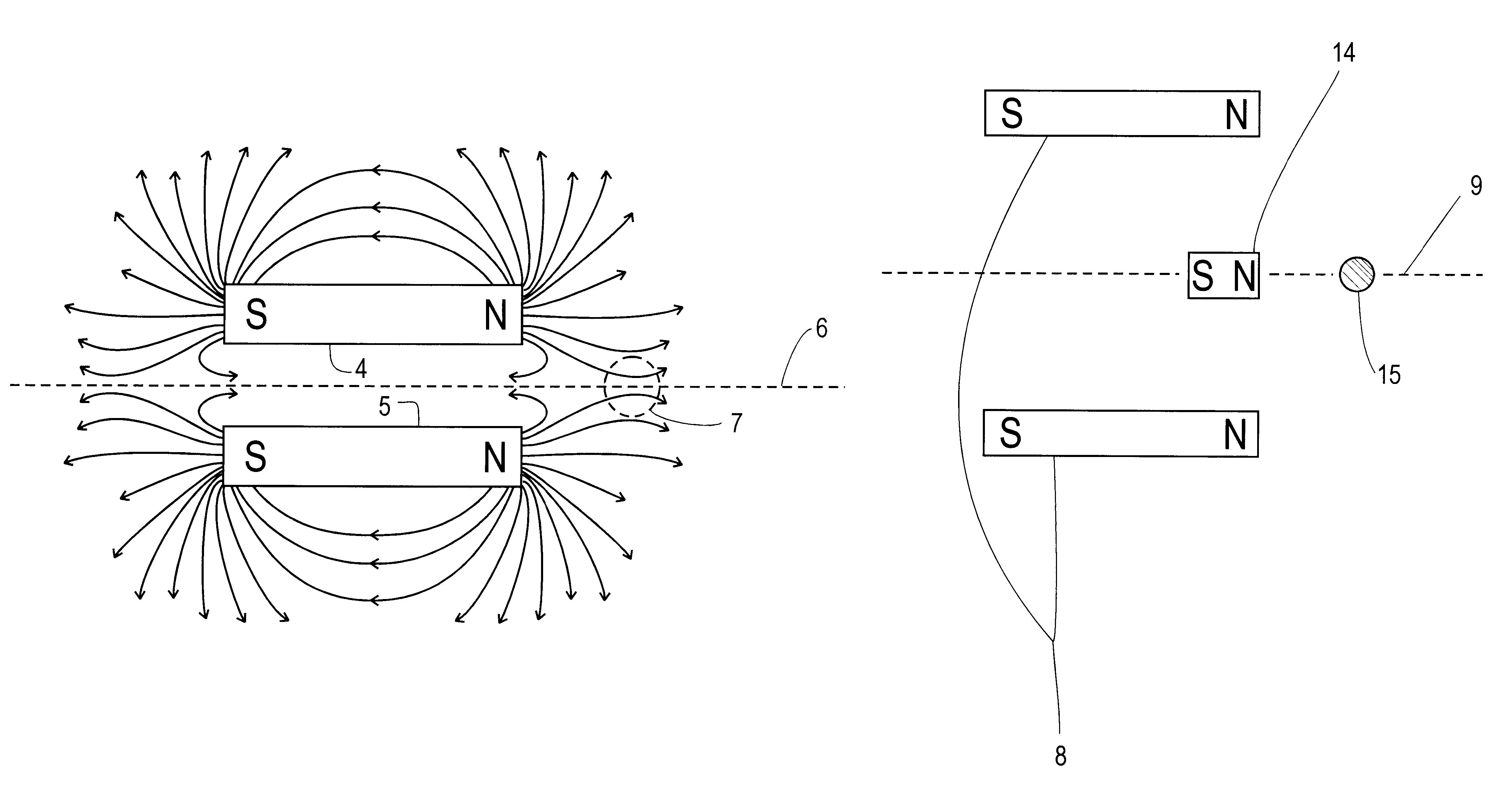
The present invention meets the need for a magnet that projects a uniform magnetic field region to a position on one side of the magnet. The present invention comprises part of a unilateral device, for example, a NMR apparatus to examine objects that cannot be otherwise accessible because of size or for other limiting reasons. In addition, use of two units of the present invention forms a magnet having a relatively open architecture compared to traditional gapped or solenoidal magnets.

The present invention comprises an efficient magnet which produces a region of uniform magnetic field that is to one side of the magnet and not between components of the magnet. The present invention comprises one or more permanent magnets and / or electromagnets to form a uniform region at a greater relative distance from the nearest magnet part. An aspect ratio defined by the distance to the uniform region and the magnet's cross section characterizes this particular advantage. Magnets of the present i...


PUM

PropertyMeasurementUnit
diameteraaaaaaaaaa
diameteraaaaaaaaaa
lengthaaaaaaaaaa

Abstract

A unilateral magnet apparatus having a remote uniform field region. The apparatus' uniform remote field region is suitable for a variety of nuclear magnetic resonance applications.

Description

1. Field of the Invention (Technical Field)The present invention relates to magnets for nuclear magnetic resonance applications, more specifically to magnets that generate at least one region with a relatively homogenous magnetic field at a position that is remotely located from the magnet assembly.2. Background ArtA major use of magnets generating regions of uniform magnetic fields is in magnetic resonance. Nuclear magnetic resonance ("NMR") is a well-established technique with applications fields such as physics, chemistry, mechanical engineering, civil engineering, nuclear engineering, petroleum engineering, food processing, pharmaceutical production, biology, and medicine. Most applications of NMR use a magnet to generate a uniform magnetic field. For superconducting magnets having a cylindrical bore, the uniform field region is within the bore whereas, for resistive electromagnets, the uniform field region is between the magnet's poles. In either configuration, a sample to be s...

Claims


Application Information

Patent Timeline
Patent Type & Authority Patents(United States)
IPC IPC(8): G01R33/38G01R33/383H01F7/20
CPCG01R33/383H01F7/202
Inventor FUKUSHIMA, EIICHIJACKSON, JASPER A.
Owner NEW MEXICO RESONANCE
Why Eureka
Try Eureka