Pre-divider architecture for low power in a digital delay locked loop

a delay lock and pre-divider technology, applied in the field of semiconductor memory, can solve the problems of limited maximum operational frequency of dll, significant power requirement, and reduced accuracy of read clock

Inactive Publication Date: 2002-12-10
INT BUSINESS MASCH CORP
View PDF16 Cites 80 Cited by
  • Summary
  • Abstract
  • Description
  • Claims
  • Application Information

AI Technical Summary

Problems solved by technology

When using a DLL circuit to generate this latency adjusted read clock output signal, the DLL typically operates at either the same or twice the system clock depending upon the design, this can lead to a significant power requirement.
One solution to reduce power requirements is to update the DLL less frequently, which in turn reduces the accuracy of the read clock.
One problem with this design is that only the delay line's control circuit 60 is operated at a reduced rate / power, leaving the phase detector 50 mimic circuit 40, and delay chain 20 operating at the original higher rate / power levels.
Another problem with this architecture is that the maximum operational frequency for which the DLL can sustain is limited.
In this design, only the feedback / control loop and associated delay line benefit from reduced power usage using the pre-divider circuit disclosed, whereas power usage in the other (main) delay line does not achieve similar results.
Problems associated with these DLL design, as discussed above, include that the delay chain (line) circuitry 20 still consumes significant power, even though the update rates have been reduced while using these techniques.

Method used


Image

  • Pre-divider architecture for low power in a digital delay locked loop
  • Pre-divider architecture for low power in a digital delay locked loop
  • Pre-divider architecture for low power in a digital delay locked loop

Examples


Embodiment Construction

This invention relates to semiconductor memories with delay lock loop including feedback for synchronizing a system clock with data output lines and reduces power usage. The invention conserves power using an input pre-divider circuit in a delay lock loop (DLL) circuit, preferably in SDRAM devices.

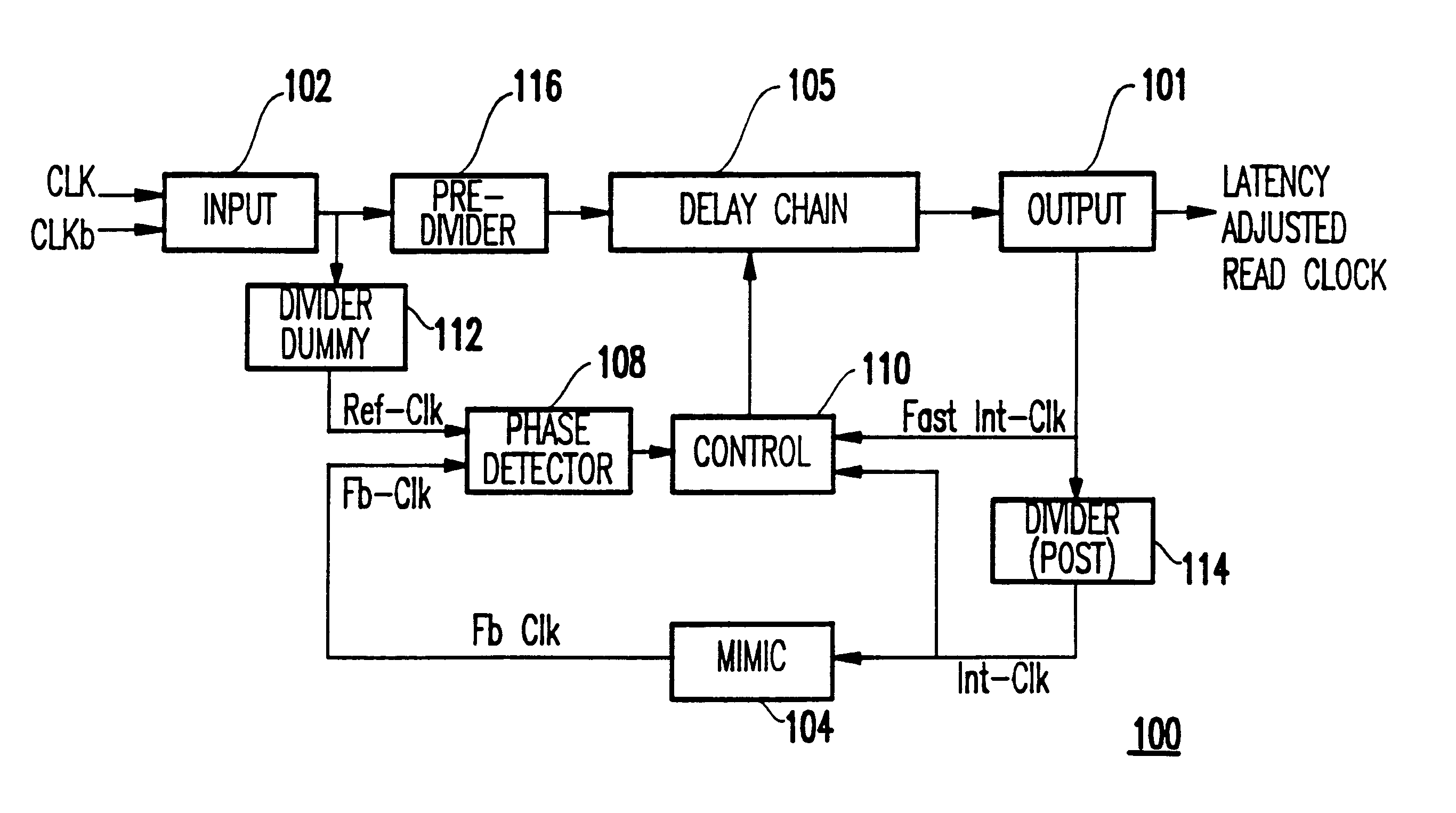
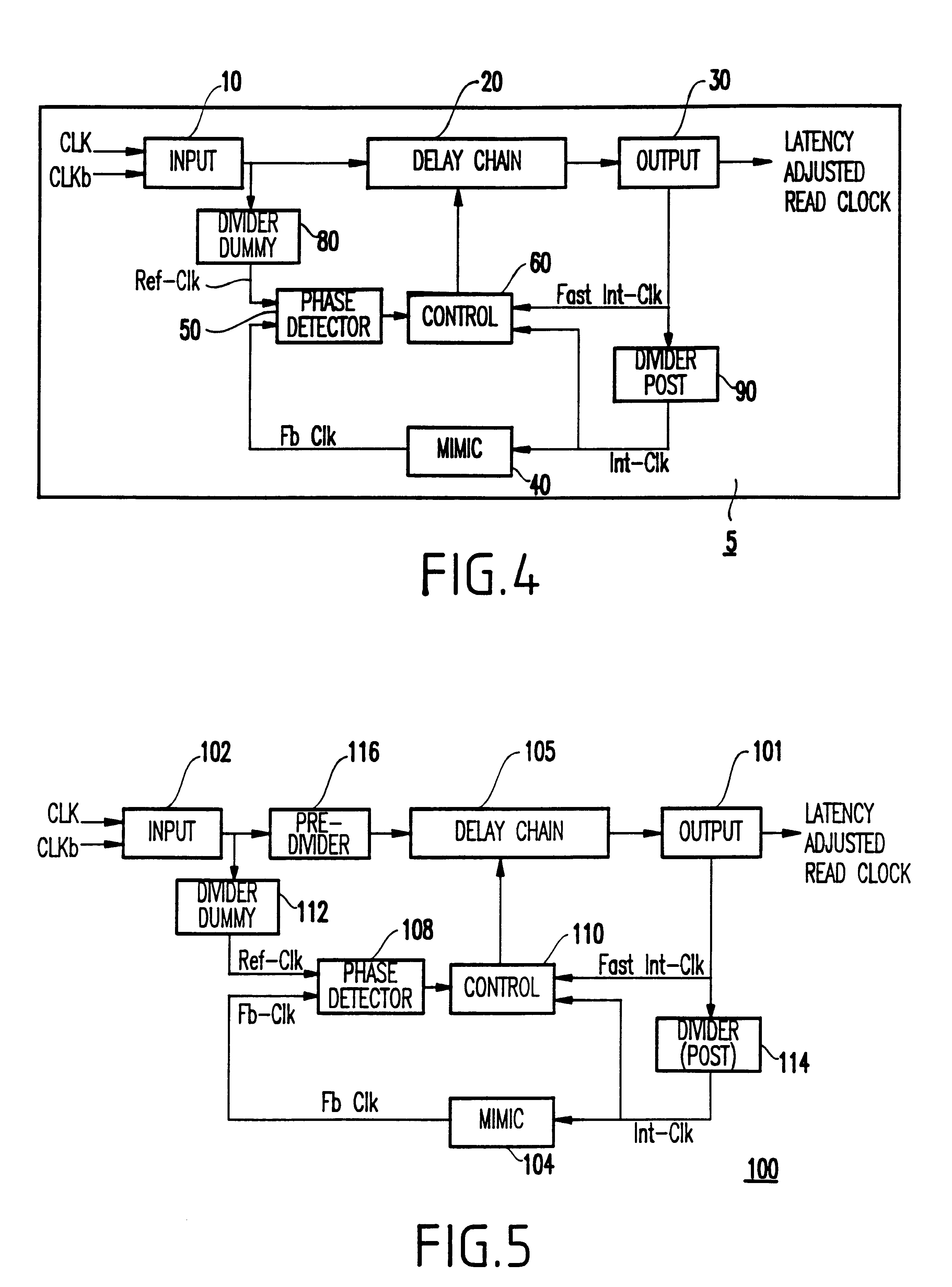
Referring now in specific detail to the drawings in which like reference numerals and block identification identify similar or identical elements throughout the several views, and initially to FIG. 5, an improved power conserving DLL circuit 100 is shown. The DLL circuit includes an input circuit 102, pre-divider 116, delay chain (line) 105 and output 101 which form the "primary signal" path leading from system input clock signals(CLK / CLKb) to DLL output signal (latency adjusted read clock signal). In addition to the Primary signal path the DLL contains two sub-paths which create a closed loop feedback system. These two sub-paths travel distinctly different routes inside the DLL but eventu...


PUM


Abstract

A delay locked loop circuit for conserving power on a semiconductor chip is provided. The circuit includes a delay chain circuit responsive to a clock input signal for generating an output clock signal having a selectively adjustable delay at an output circuit; a feedback loop circuit connects to and controls said delay chain circuit; and a pre-divider circuit connected to said delay chain circuit, wherein said pre-divider circuit is configured to disable the delay chain circuit when the output clock signal is inactive and the memory device is in an idle state (i.e., all banks closed).

Description

1. Field of the InventionThe present invention relates to semiconductor memories and more particularly, to an improved delay locked loop (DLL) circuit design for power conservation that synchronizes a system clock with data output lines.2. Description of the Related ArtSemiconductor memories, such as synchronous dynamic random access memories (SDRAMs), rambus DRAM, a synclink DRAM and Double Data Rate (DDR-SDRAM) memories, typically include delay lock loop (DLL) circuits. DLLs function to cancel on-chip amplification, signal processing and buffering delays. DLLs also improve input / output timing margins, the output from which include a latency adjusted read clock signal. A "read" operation in DDR-SDRAMs are designed such that signal transitions present on output data lines (DQs) are synchronized to transitions of the system clock. The DLL circuit requires significant additional current to power the memory device, where lowest power requirements are desirable. When using a DLL circuit...

Claims


Application Information

Patent Timeline
Patent Type & Authority Patents(United States)
IPC IPC(8): G11C7/22G11C7/00H03L7/08H03L7/081
CPCG11C7/22G11C7/222G11C7/225H03L7/0802H03L7/0812H03L7/0814H03L7/0816
Inventor FISCUS, TIMOTHY E.
Owner INT BUSINESS MASCH CORP
Why Eureka
Try Eureka