Ion extraction assembly

Inactive Publication Date: 2002-12-31
APPLIED MATERIALS INC
View PDF7 Cites 54 Cited by
  • Summary
  • Abstract
  • Description
  • Claims
  • Application Information

AI Technical Summary

Problems solved by technology

While this is an improvement on a conventional electrode assembly, it is still limited to two discrete sets of extraction conditions.
However, neither of these alternatives allows independent control of the slit width and transverse position of the electrode, as the movement caused by one actuator to change either the slit width or the tran

Method used


Image

  • Ion extraction assembly
  • Ion extraction assembly
  • Ion extraction assembly

Examples


Embodiment Construction

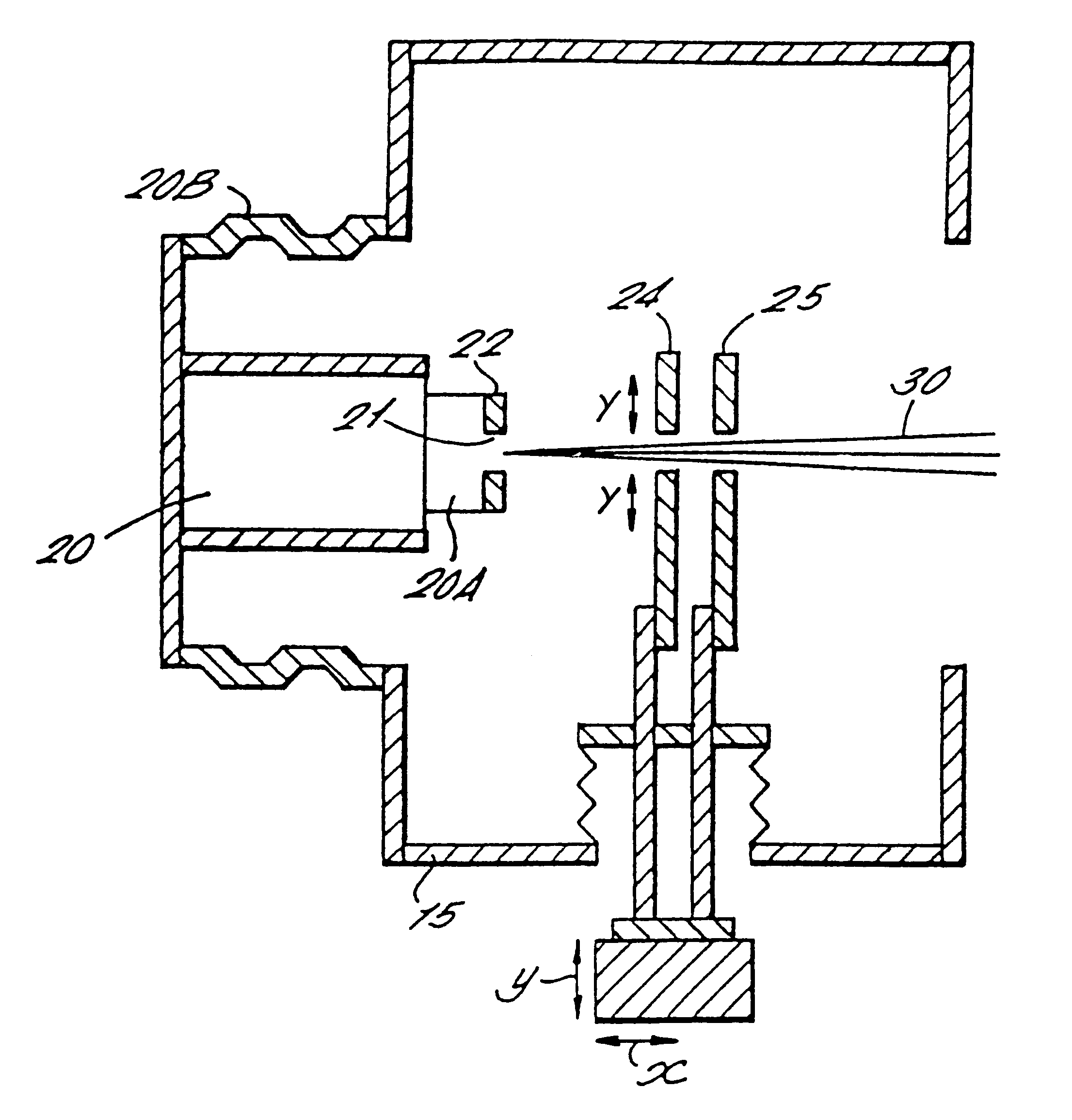
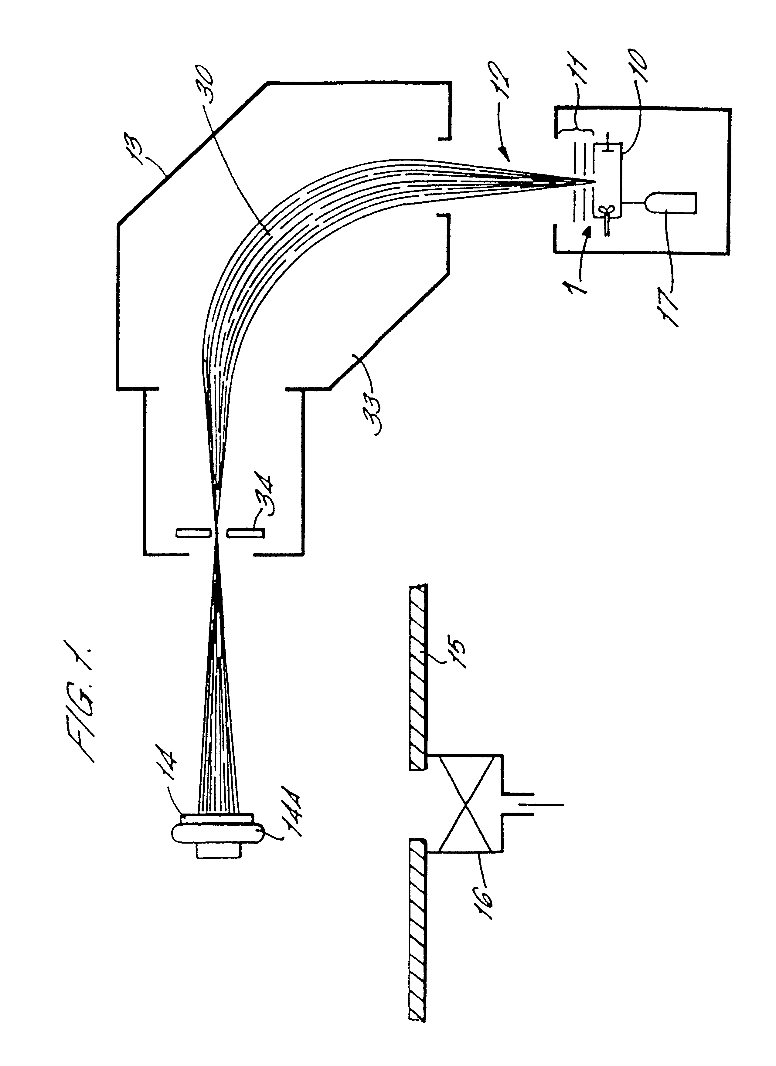
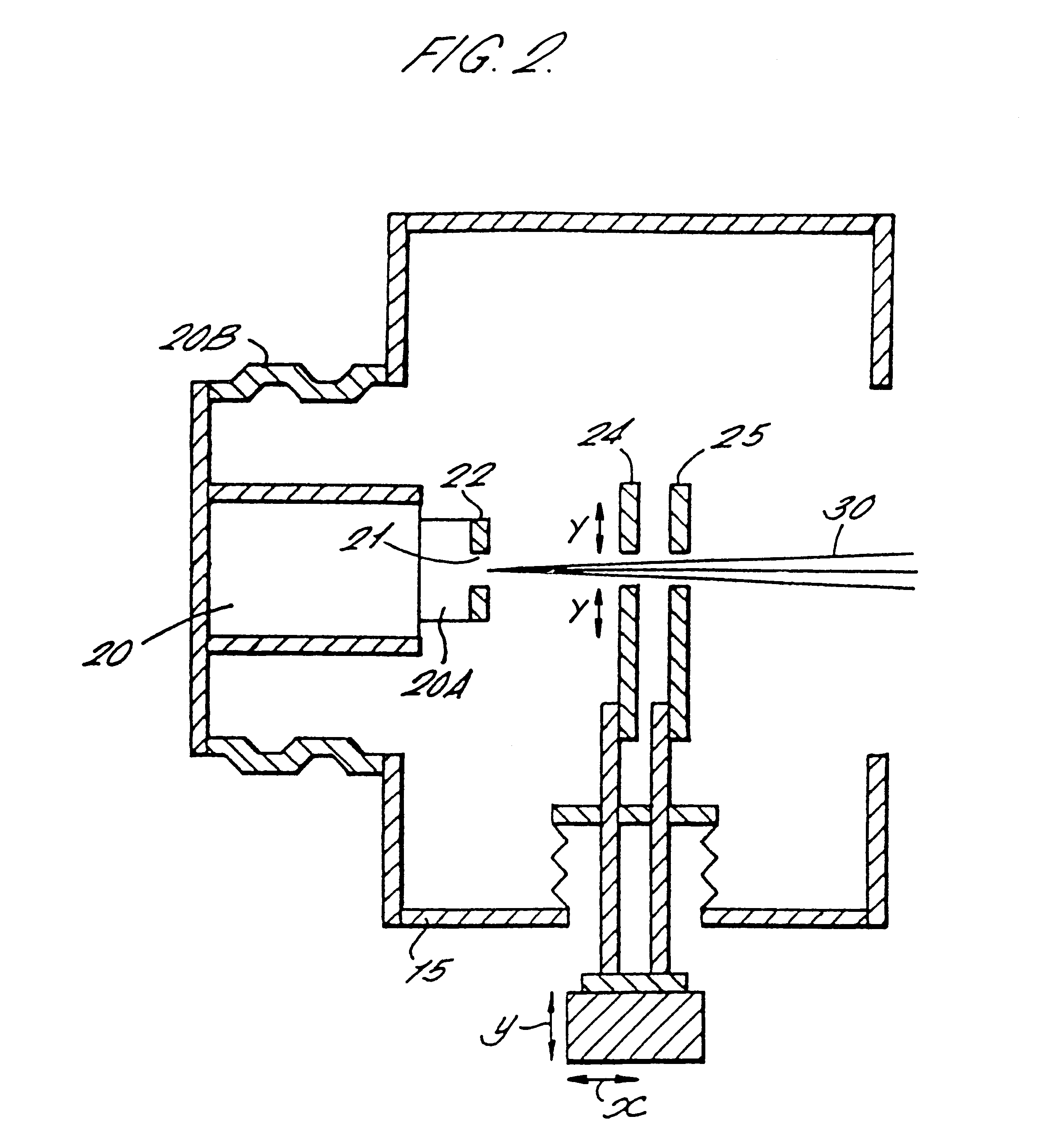
Referring to FIG. 1, an ion implanter apparatus comprises an extraction assembly 1 comprising an ion beam source 10 with a set of extraction electrodes 11, directing an ion beam 12 through an ion mass selector 13 to impinge on a target substrate 14 mounted on a target substrate holder 14A. As is well known to workers in this field, the above elements of the ion implanter are housed in a vacuum housing of which a part 15 only is illustrated in FIG. 1. The vacuum housing may be evacuated by a vacuum pump 16.

The ion source 10 may comprise any known ion source such as a Freeman source or a Bernas source. The ion source 10 comprises an arc chamber to which is fed a supply of atoms of or molecules containing the element, ions of which are to be implanted in the target substrate 14. The molecules may be supplied to the arc chamber in gaseous or vapour form, e.g. from a gas bottle 17.

The set of extraction electrodes 11 is located immediately outside a front face of the arc chamber of the io...


PUM

PropertyMeasurementUnit
Fractionaaaaaaaaaa
Angleaaaaaaaaaa
Widthaaaaaaaaaa

Abstract

An ion electrode extraction assembly comprising an ion source 20 and at least one electrode 50 having a gap through which a beam of extracted ions passes in use. An electrode manipulator assembly 55 is provided to move the electrode so as to vary the width of the gap transversely to the ion beam, move the electrode transversely to the ion beam, and move the electrode in the direction of the ion beam. The three degrees of movement being carried out independently of one another.

Description

This invention relates an ion extraction assembly for generating a beam of ions. In particular, the invention relates to an improved electrode manipulator for such an assembly.DESCRIPTION OF THE PRIOR ARTExtraction assemblies are known in the art having several electrodes positioned adjacent to an ion source to extract a beam of ions from the source. Each electrode has a slit through which the beam of ions passes.WO 97 / 04474 discloses an ion beam apparatus in which a pair of extraction electrodes are mounted so as to be movable in a first direction towards or away from the ion source (i.e. the direction of the ion beam), and independently movable in a transverse direction (i.e. across the ion beam).Each of the extraction electrodes is provided with a pair of apertures which can be selectively brought into line with the ion beam upon transverse movement of the electrodes. The apertures have different sizes each defining the extraction optics for a particular range of extraction condi...

Claims


Application Information

Patent Timeline
IPC IPC(8): H01J49/28H01J37/08H01J37/147H01J37/15H01J49/26C23C14/48H01J27/02G21K5/04H01J37/317H01L21/265
CPCH01J37/08H01J37/15H01J49/28H01J2237/31701
Inventor RYDING, GEOFFREYSMICK, THEODORE H.FARLEY, MARVINSAKASE, TAKAO
Owner APPLIED MATERIALS INC
Why Eureka
Try Eureka