Method for limiting the closing force of movable components

Inactive Publication Date: 2003-01-07
ROBERT BOSCH GMBH
View PDF14 Cites 19 Cited by
  • Summary
  • Abstract
  • Description
  • Claims
  • Application Information

AI Technical Summary

Benefits of technology

The method according to the invention for limiting the closing force of movable parts, with the features of the main claim, has the advantage that by presetting a time limit value curve, an optimal adaptation to different spring ratios is possible. The limit value curve can be selected so that when hard objects are pinched with a high spring ratio, there is sufficient time to activate a pinch prevention measure. When objects are pinched with a low spring ratio, the drive can be switched off at much lower pinching forces. By presetting a particular limit value curve, an individual limit value can thus be predetermined for each spring ratio.
It is advantageous if the determination of the respective current motor speeds n is executed based on periodic edge alternations. Such edge alternations are typically produced by a two-pole or multi-pole annular magnet which is mounted on a rotatable axle of the motor. Upon rotation of the axle, signal changes are produced which are detected by a Hall sensor. The respective current motor speed can be determined from the periodic edge alternations, for example by measuring the period duration.
If the summated value .SIGMA..DELTA.n exceeds a threshold value S, then the method transitions into the second stage in which the time meter and the limit value curve transmitter are started. The time meter does not necessarily have to be started, it can also run continuously. The only decisive thing is that the time meter is sent a signal indicating the time at which the second stage is triggered or the limit value curve transmitter is started.
An additional, very significant advantage is achieved if the limit value curve automatically adapts to changing operating conditions. For example, sluggishness due to aging effects can then be recognized and taken into account.
A current and advantageous measure for limiting the closing force of the adjusting drive is to stop or reverse the adjusting drive or also to move the movable part back into an initial position.

Problems solved by technology

All of these methods, however, have the disadvantage that the limit values are predetermined in a fixed manner independent of the type of objects being pinched.
It is therefore impossible to adapt the closing force limitation to objects of a different hardness or softness.
On the other hand, when very soft objects are being pinched, it can take a very long time before a pinch prevention measure is activated.
Thus the current methods do not take different spring ratios into consideration.
This is a big disadvantage because an optimal limit value can only be matched to one particular spring ratio as a switch-off criterion.

Method used


Image

  • Method for limiting the closing force of movable components
  • Method for limiting the closing force of movable components
  • Method for limiting the closing force of movable components

Examples


Embodiment Construction

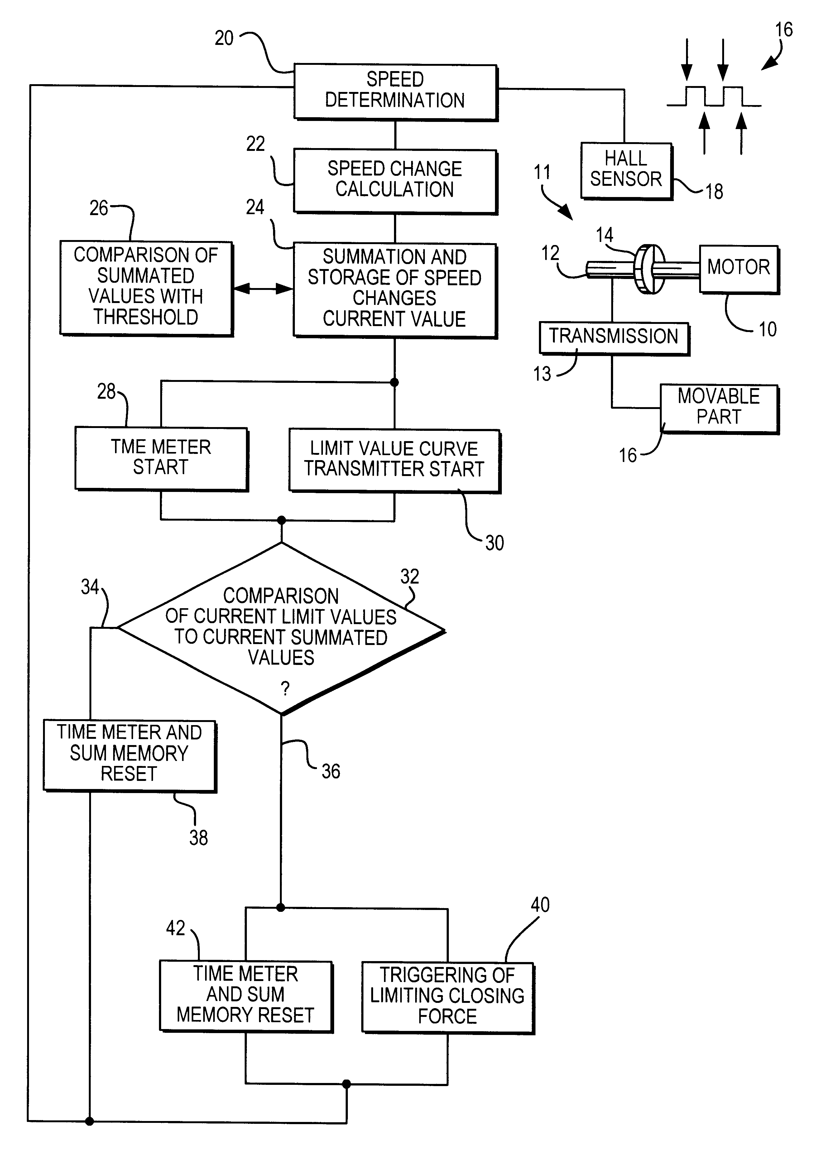
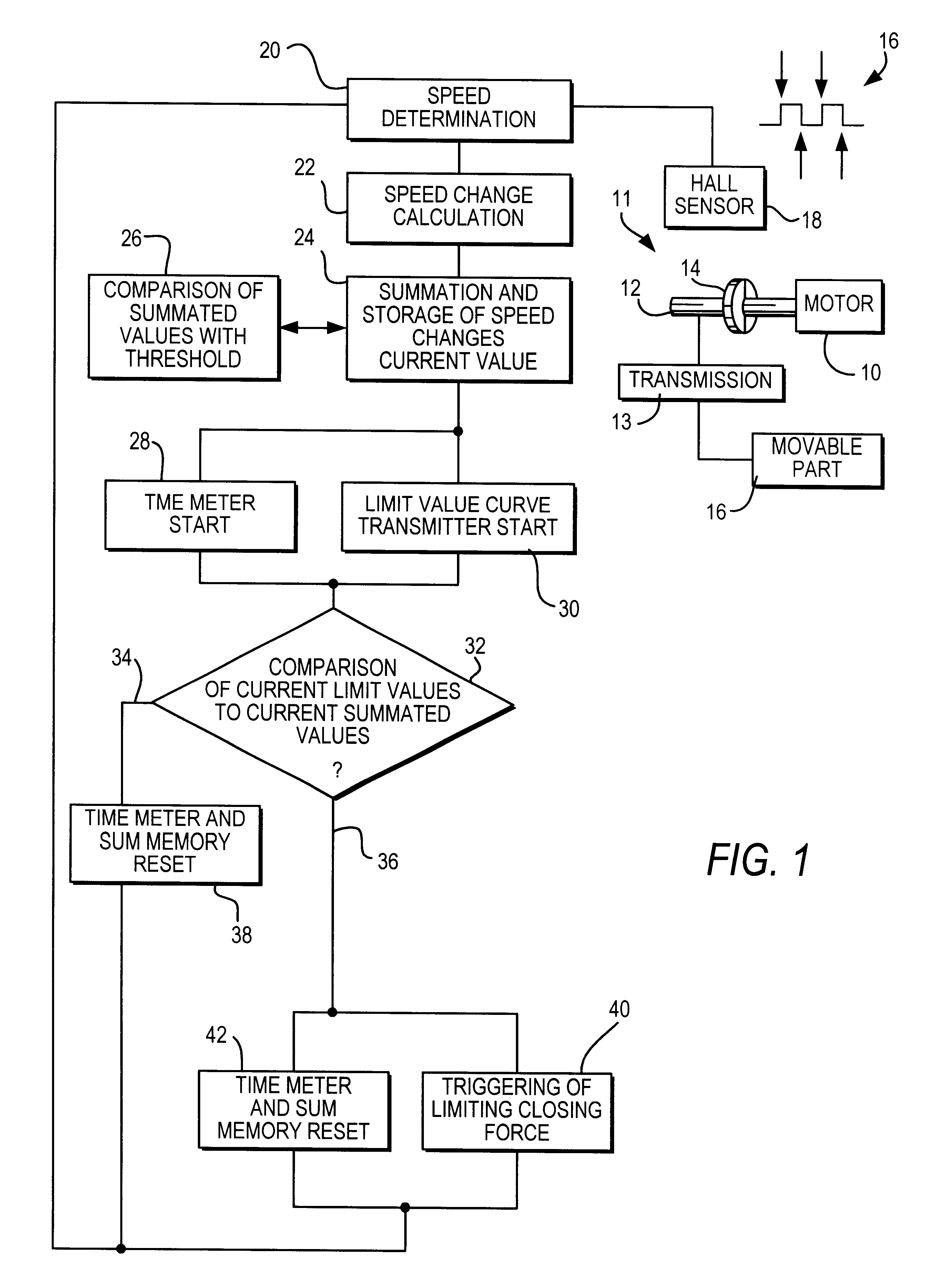
The exemplary embodiment of a method according to the invention for limiting the closing force of movable parts shown in FIG. 1 contains schematic depictions of individual parts of an adjusting drive and a flow chart in a number of steps.

A motor 10 of an adjusting drive 11 drives a shaft 12 which is connected via a transmission unit 13 to a movable part 16. A two-pole annular magnet 14 is non-rotatably mounted on the shaft 12 and, upon rotation of the shaft 12, generates periodic edge alternations 16 in a Hall sensor 18.

In a first stage of the method, the speed n of the motor 10 is determined in the process step 20, based on the periodic edge alternations 16 of the Hall sensor 18. In a second process step 22, a value .DELTA.n that is typical for the current motor speed change is calculated based on the respective current motor speeds n. This calculation yields the difference between a current speed value n.sub.i and an immediately preceding speed value n.sub.i-1. In the borderline c...


PUM


Abstract

A method for limiting the closing force of movable components (16), in particular windows and sliding roofs in vehicles is provided. The windows and roofs are powered by an electric motor driven servo drive. The inventive method comprises at least the following steps: determination of the actual motor rotation speed n by evaluating periodic signals from a sensor connected to a servo drive; calculation of a typical parameter on which reflects a change in motor rotation speed; summation and saving of an actual typical parameter in a sum storage device; starting of a timing device and a threshold sensor, in the event that the summed parameter value totals exceed a parameter threshold value; comparison of an actual threshold value g(t) with an actual, summed parameter value; triggering of a mechanism to limit the closing force and resetting of the timing device and the summed value storage device, if the respective current value of the summed parameters are the same as or equal to or larger than the respective current threshold value g(t); termination of the comparing procedure and resetting of the timing device in addition to the summed value memory, if the respective value of the summed parameter is smaller than the respective current threshold value and is within a predefined tolerance and additionally, a predefined time unit remains constant.

Description

PRIOR ARTThe invention relates to a method for limiting the closing force of movable parts, in particular windows and sliding roofs in motor vehicles, according to the preamble to the independent claim.Many of the previously known methods are essentially based on the fact that a particular measurement quantity that typically changes in the event of a pinch is monitored and when a particular, preset limit value is exceeded, steps are taken to limit the closing force. These typical values are, for example, the speed of a motor driving the movable parts or the current- or power consumption of this motor. Frequently, the limit values for triggering the closing force limitation are also variable and can be adapted, for example, to changing friction conditions or aging processes.All of these methods, however, have the disadvantage that the limit values are predetermined in a fixed manner independent of the type of objects being pinched. It is therefore impossible to adapt the closing forc...

Claims


Application Information

Patent Timeline
IPC IPC(8): H02H7/085H02H7/093H02H3/00H02H7/08B60J1/17B60J7/02E05F15/20
CPCH02H7/0851H02H3/006H02H7/093E05F15/70
Inventor LAMM, HUBERT
Owner ROBERT BOSCH GMBH
Why Eureka
Try Eureka