Passive cardiac assistance device

a cardiac assistance and passive technology, applied in the field of passive cardiac assistance devices, can solve the problems of increasing the load, increasing the oxygen consumption of the heart, and injuring patients with ventricular dilatation,

Inactive Publication Date: 2003-01-21
ABIOMED
View PDF30 Cites 174 Cited by
  • Summary
  • Abstract
  • Description
  • Claims
  • Application Information

AI Technical Summary

Benefits of technology

Ventricular dilatation is a clinically dangerous condition for end stage cardiac failure patients. The output of the heart is effected by: (a) end-diastolic volume (ventricular volume at the end of the filling-phase), (b) end-systolic volume (ventricular volume at the end of the ejection phase), and (c) heart rate. When (a) is very large, (b) also tends to be larger and (c) tends to be larger than normal. All three of these factors contribute to large increases in the tension-time integral and therefore to increased oxygen consumption.
To avoid the problem of potential irritability and damage to the external myocardium cells by virtue of the artificial wrap and its long term constraining contact with the myocardium, one embodiment of the invention employs a tissue engineered lining to protect the myocardium. This tissue engineered lining consists of a polymer scaffold seeded with myocardial cells harvested from the patient's own myocardium using tissue engineering technology. That lining then generates a biological myocardio-interfacing surface and remains firmly attached to the polymer interfacing with the surface from which the wrap is made. Such a lining would integrate biologically to the heart's myocardial cells in a manner analogous to other devices currently being investigated which use cell scaffolds for in vitro and in vitro tissue engineering.
It is yet another object of this invention to provide a ventricular assist device which is compact, requires relatively low energy input and does not require percutaneous components.
It is a further object of this invention to provide a passive girdle to be wrapped around a heart suffering from ventricular dilatation to limit this dilatation and thus improve the performance characteristics of the heart.
It is another object of this invention to provide a passive girdle or vest which can, over a period of time, have its diameter decreased to effect some decrease in dilatation of the ventricle.

Problems solved by technology

Patients having a heart condition known as ventricular dilatation are in a clinically dangerous condition when the patients are in an end stage cardiac failure pattern.
The ventricular dilatation increases the load on the heart (that is, it increases the oxygen consumption by the heart), while at the same time decreasing cardiac efficiency.
A significant fraction of patients in congestive heart failure, including those who are not in immediate danger of death, lead very limited lives.
This dilatation condition does not respond to current pharmacological treatment.
During ventricular dilatation the ventricular radius increases and the energy dissipated by the heart muscle just to maintain this elastic tension during diastole is abnormally increased, thereby increasing oxygen consumption.
This risk is most associated with use of artificial blood contacting surfaces.
One problem affecting thromboembolism risk in heart assists arises from the use of prosthetic, biologic or mechanical pericardial valves.
A second problem associated with implanted cardiac assist devices Is the problem of infection, particularly where the implanted device has large areas of material in contact with blood and tissue.
A third problem area in ventricular assist devices is the calcification of these devices.
However, once again, the blood is exposed to the surfaces of the pump, particularly the bearing and seal area.
However, for most present ventricular assist device systems, stoppage of even a few minutes results in formation of blood clots in the device, rendering any restart of the system a very risky undertaking.

Method used


Image

  • Passive cardiac assistance device
  • Passive cardiac assistance device
  • Passive cardiac assistance device

Examples


Embodiment Construction

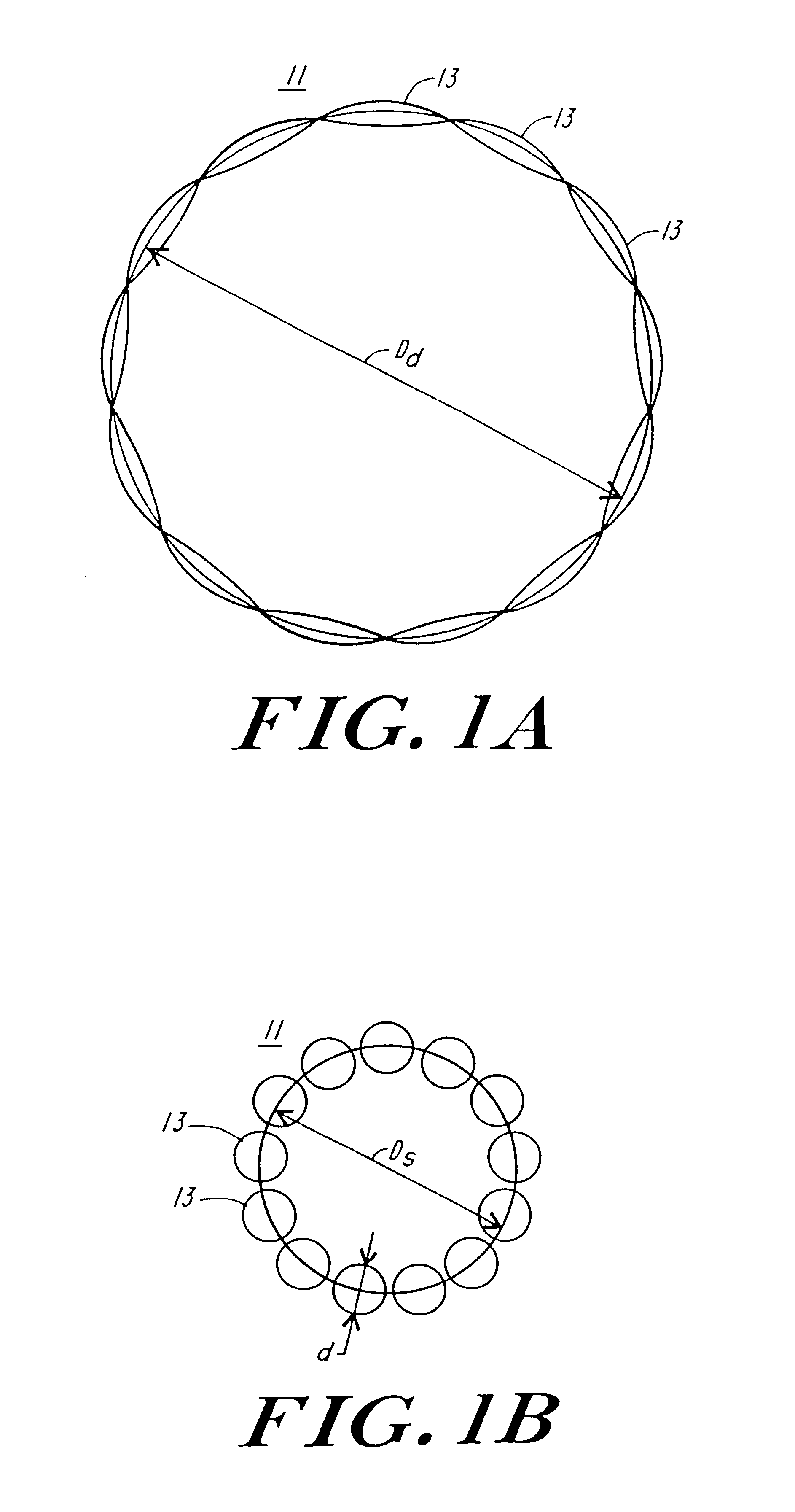
FIG. 1A and FIG. 1B illustrate diagrammatically the operation of the artificial myocardium. The artificial myocardium 11 is formed of a series of tubes planed together in series to form, in this instance a complete circle, which in FIG. 1A has a diameter D.sub.d. In FIG. 1B the feature of the tubes is filled hydraulic fluid producing a circular cross-section, shortening the total perimeter of the circular cuff to a circle having a diameter D.sub.S. Referring to FIG. 1B, if the diameter of the tube with the circular cross-section is d, then the diameter of the circular cuff is approximately equal to nd / .pi., where n equals the total number of tubes. On the other hand, when the tubes are no longer filled with hydraulic fluid and are collapsed then the diameter D.sub.d is approximately equal to ##EQU2##

These expressions follow from the consideration that the series of n tubes in the inflated condition, as illustrated in FIG. 1B form a circle with the number of tubes times diameter of e...


PUM


Abstract

Artificial implantable active and passive girdles include a heart assist system with an artificial myocardium employing a number of flexible, non-distensible tubes with the walls along their long axes connected in series to form a cuff and a passive girdle is wrapped around a heart muscle which has dilatation of a ventricle to conform to the size and shape of the heart and to constrain the dilatation during diastole. The passive girdle is formed of a material and structure that does not expand away from the heart but may, over an extended period of time be decreased in size as dilatation decreases.

Description

FIELD AND BACKGROUND OF THE INVENTIONThe present invention relates to cardiac devices in general, and more specifically to passive and active cardiac girdles.Patients having a heart condition known as ventricular dilatation are in a clinically dangerous condition when the patients are in an end stage cardiac failure pattern. The ventricular dilatation increases the load on the heart (that is, it increases the oxygen consumption by the heart), while at the same time decreasing cardiac efficiency. A significant fraction of patients in congestive heart failure, including those who are not in immediate danger of death, lead very limited lives. This dilatation condition does not respond to current pharmacological treatment. A small amount, typically less than 10%, of the energy and oxygen consumed by the heart, is used to do mechanical work. Thus the balance, which is the major part of the energy consumed by the heart is used in maintaining the elastic tension of the heart muscles for a ...

Claims


Application Information

Patent Timeline
Patent Type & Authority Patents(United States)
IPC IPC(8): A61F2/00A61M1/10A61F2/24
CPCA61F2/2481A61M1/1044A61M1/1068A61F2002/0068Y10S623/904A61M1/106A61M2205/33A61M2205/3303A61M60/869A61M60/468A61M60/191A61M60/289A61M60/569A61M60/865A61M60/515
Inventor KUNG, ROBERT T. V.LEDERMAN, DAVID M.ROSENBERG, MEIR
Owner ABIOMED
Why Eureka
Try Eureka