Endoscope having microscopic and macroscopic magnification

a technology of endoscope and magnification, which is applied in the field of endoscope, can solve the problems of insufficient macroscopic magnification provided by the previously known endoscope, insufficient examination of the organ tissue in sufficient detail to determine, and unnecessary harm to the patient, so as to prevent unnecessary biopsies and/or organ removal, the effect of convenient sterilization

Inactive Publication Date: 2003-03-11
INNER VISION IMAGING
View PDF36 Cites 94 Cited by
  • Summary
  • Abstract
  • Description
  • Claims
  • Application Information

AI Technical Summary

Benefits of technology

The magnification achieved by the endoscope assembly can be varied between macroscopic, or low, magnification and microscopic, or high, magnification. Macroscopic magnification is utilized to provide an optical view to the surgeon of a relatively wide area within the body cavity whereas in the microscopic magnification mode, the system is capable of resolving structure at the cellular level. In microscopic mode, the system provides high resolution imaging not only of the surface layer of body tissue, but also of layers beneath the surface by means of a confocal assembly contained within the housing. In-depth imaging is enhanced by the use of near-infrared illumination, at which wavelengths body tissue is typically more transparent than at visible wavelengths.
The stage also provides a sterile barrier between the body cavity and the endoscope tube. Because of its simplicity, the stage may be readily sterilized between uses or it may be disposable.
In the preferred embodiment of the invention, the optical images formed by the optical assemblies of the endoscope apparatus are focused onto CCD detectors and transmitted as electronic signals to a computer system. The computer system, in turn, communicates the digitized images via a network and / or telephone lines to a pathologist who may be remote from the patient. Consequently, the pathologist is capable of viewing the images through the endoscope on a real-time basis. Since the endoscopic imaging system of the present invention enables real-time pathological examination and diagnosis of suspect tissue, unnecessary biopsies and / or organ removal are prevented.

Problems solved by technology

Perhaps the most significant disadvantage of these previously known endoscopes is that, since the optical lenses are fixed within the endoscope, the field of magnification for the endoscope remains constant.
For example, in certain situations where cancerous growths within body organs are suspected, the macroscopic magnification provided by the previously known endoscopes is insufficient to examine the organ tissue in sufficient detail to determine whether the tissue abnormality is cancerous or benign.
First, in the event that the organ abnormality is benign, the biopsy and possible removal of the entire organ from the body results in unnecessary harm and even loss of organ function to the patient.
Second, since the subsequent pathological examination of the body tissue oftentimes occurs long after the end of the operation, in the event that the pathological examination reveals a cancerous growth within the body tissue, it is oftentimes necessary for the surgeon to re-enter the body cavity and remove additional body tissue in an attempt to completely eradicate the cancer.
This disadvantageously, however, subjects the patient to a second operation.
An additional disadvantage of previously known endoscopes is that the illumination and viewing paths are separate and each path uses only a portion of the available diameter of the endoscope.

Method used


Image

  • Endoscope having microscopic and macroscopic magnification
  • Endoscope having microscopic and macroscopic magnification
  • Endoscope having microscopic and macroscopic magnification

Examples


Embodiment Construction

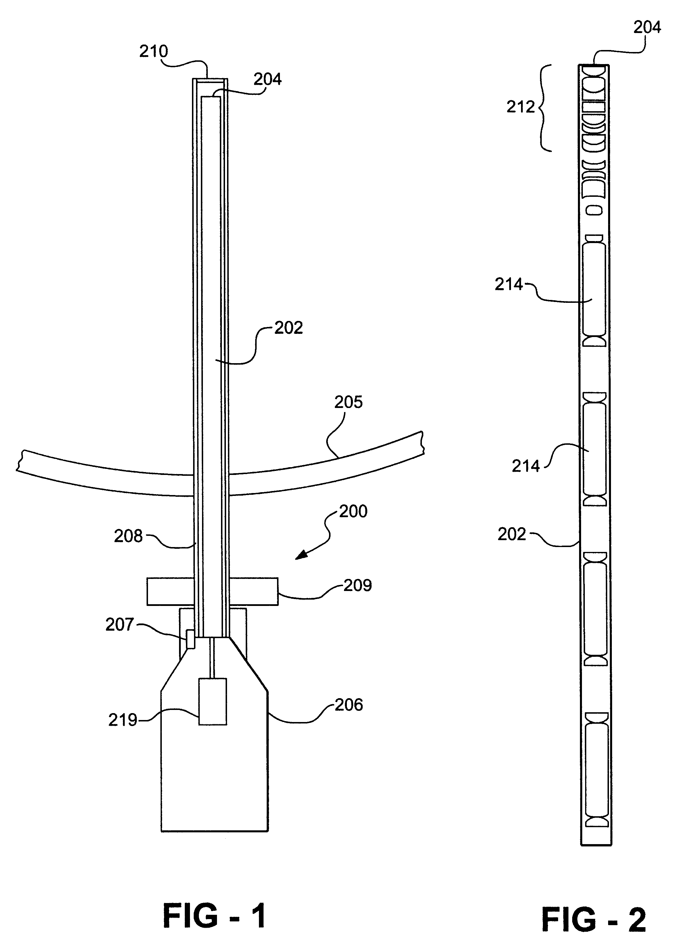
With reference first to FIG. 1, a preferred embodiment of the endoscope assembly 200 of the present invention is there shown. The endoscope 200 includes an elongated endoscope lens tube 202 having a free end 204 and an opposite end that is attached to a housing 206. The housing is designed to be manipulated by hand by the surgeon or other medical personnel, although it may alternatively be attached to a mechanical support or to a robotic arm. An elongated tubular stage 208 is dimensioned to be slidably received over the free end 204 of the lens tube 202 and is detachably secured to the housing 206 by a mechanical coupling 207, such as a bayonet coupling. The stage 208 has a transparent window 210 that is positioned over the free end 204 of the lens tube 202. The lens tube 202 together with the stage 208 is insertable into the patient 205 through a cannula while the housing 206 remains exterior of the patient.

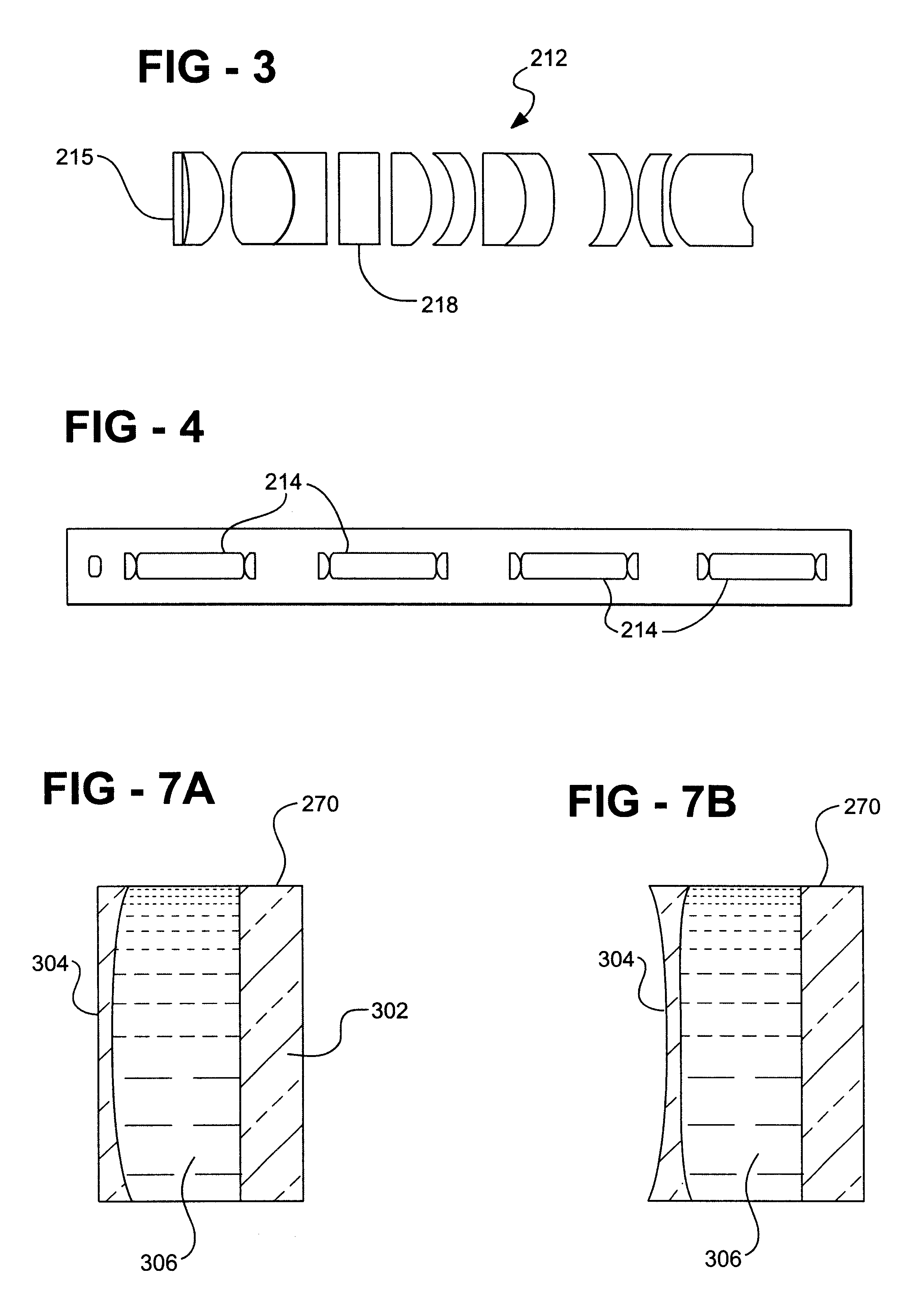
With reference now to FIGS. 2-4, a plurality of optical lenses are disposed...


PUM


Abstract

An endoscope assembly is disclosed having a housing adapted to be manipulated by medical personnel, such as a surgeon. An elongated lens tube has one end secured to the housing while an elongated stage is removably secured to the housing so that the stage encompasses and is coaxial with the tube. The stage together with the lens tube are adapted for insertion into the cavity of a body. A lens assembly provided within the lens tube relays the optical image from the free end of the stage to the housing. A lens assembly within the housing, furthermore, varies the magnification of the image between macroscopic magnification and microscopic magnification in which tissue may be examined on a cellular level. For macroscopic magnification, white light is transmitted through the lens tube as well as reflected back from the target tissue through the lens tube and to the housing. For microscopic examination, laser radiation is utilized in lieu of the white light illumination. A line scanning confocal assembly contained within the housing enables microscopic examination of the target tissue at varying levels into the tissue from the end of the stage.

Description

I. Field of the InventionThe present invention relates generally to medical instruments and, more particularly, to an endoscope.II. Discussion of Related ArtLaparoscopic surgery has enjoyed increasing acceptance, particularly for surgery involving the abdominal cavity. In such surgery, one or more incisions are made through the patient's skin. Thereafter, various medical instruments, including endoscopes, are inserted through the incisions and into a body cavity, such as the abdominal cavity.In order for the surgeon to see into the abdominal cavity, the surgeon typically uses an endoscope which is inserted through a cannula and into the abdominal cavity. The previously known endoscopes typically comprise an elongated tube having one or more fixed lenses. These lenses provide an optical view of the interior of the body cavity to an eyepiece or other display means accessible to the surgeon outside the body. Illumination for the endoscope is typically provided by optical fibers which e...

Claims


Application Information

Patent Timeline
Patent Type & Authority Patents(United States)
IPC IPC(8): A61B1/00G02B23/24A61B5/00
CPCA61B1/00135A61B1/00188G02B23/2446G02B23/2438A61B5/0068A61B1/3132A61B5/0002A61B5/0084A61B2562/146
Inventor FARKAS, RICHARDFISHER, RICHARDHENKE, STEVEN
Owner INNER VISION IMAGING
Why Eureka
Try Eureka