Drive system

a technology of drive system and rotor arrangement, which is applied in the direction of gas pressure propulsion mounting, electric devices, air cooling, etc., can solve the problems of lowering the efficiency of electric machines at high speeds and difficulty in achieving the desired operating temperature at the rotor arrangement in a relatively short tim

Inactive Publication Date: 2003-03-11
ZF FRIEDRICHSHAFEN AG
View PDF14 Cites 11 Cited by
  • Summary
  • Abstract
  • Description
  • Claims
  • Application Information

AI Technical Summary

Benefits of technology

Drive units which are cooled generally include internal combustion engines which are at first still cold when put into operation. That is, the cooling fluid, which is usually cooling water, is at a prevailing ambient temperature when the ICE is initially started. Immediately following the start of the internal combustion engine, the temperature thereof rises relatively rapidly. Accordingly, the temperature of the cooling fluid in the internal combustion engine also rises at a rate which is quicker than the temperature in the region of the rotor arrangement. To utilize this rise in temperature for bringing the rotor arrangement relatively quickly to the desired operating temperature, in a first operating phase in which the temperature of the heat transfer fluid is higher than the temperature prevailing in the region of the rotor arrangement, and the temperature prevailing in the region of the rotor arrangement is lower than the desired operating temperature, the heat transfer fluid is fed to the rotor arrangement for the purpose of heat transfer. This effect may be used not only when an internal combustion engine to be cooled is used as a drive unit, but always whenever a heat transfer fluid such as, for example, a cooling fluid has a higher temperature than that temperature which prevails in the region of the rotor arrangement.
It is preferably provided in the present invention that the desired operating temperature is a function of the speed of the rotor arrangement. The desired operating temperature may be higher during a higher speed of the rotor arrangement than during a lower speed of the rotor arrangement. The invention makes use here of the fact that, as already mentioned, the magnetic flux or the field strength of the permanent magnets of the rotor arrangement generally increases with decreasing temperature. However, at lower speeds the induced back-e.m.f. is still low, in any case lower than the operating voltage applied to the stator arrangement, so that here prescribing a lower desired operating temperature firstly has the advantage that a greater efficiency of the electric machine can be achieved because of the higher field strength of the permanent magnets.
To avoid damaging the electric machine, particularly in the case of defective drives, the desired operating temperature is a temperature which is situated approximately 10-50.degree. C. below a temperature at which an irreversible impairment of the magnetization of the rotor arrangement operated by permanent magnet may occur.

Problems solved by technology

The fraction of the field weakening current increases with the speed of the machine, thereby lowering the efficiency of the electric machine at high speeds.
Thus, if the procedure of feeding this cooling fluid as heat transfer fluid to the rotor arrangement or to the heat transfer arrangement for the rotor arrangement were to be continued, it would be difficult to achieve the desired operating temperature at the rotor arrangement in a relatively short time.

Method used


Image

  • Drive system
  • Drive system
  • Drive system

Examples


Embodiment Construction

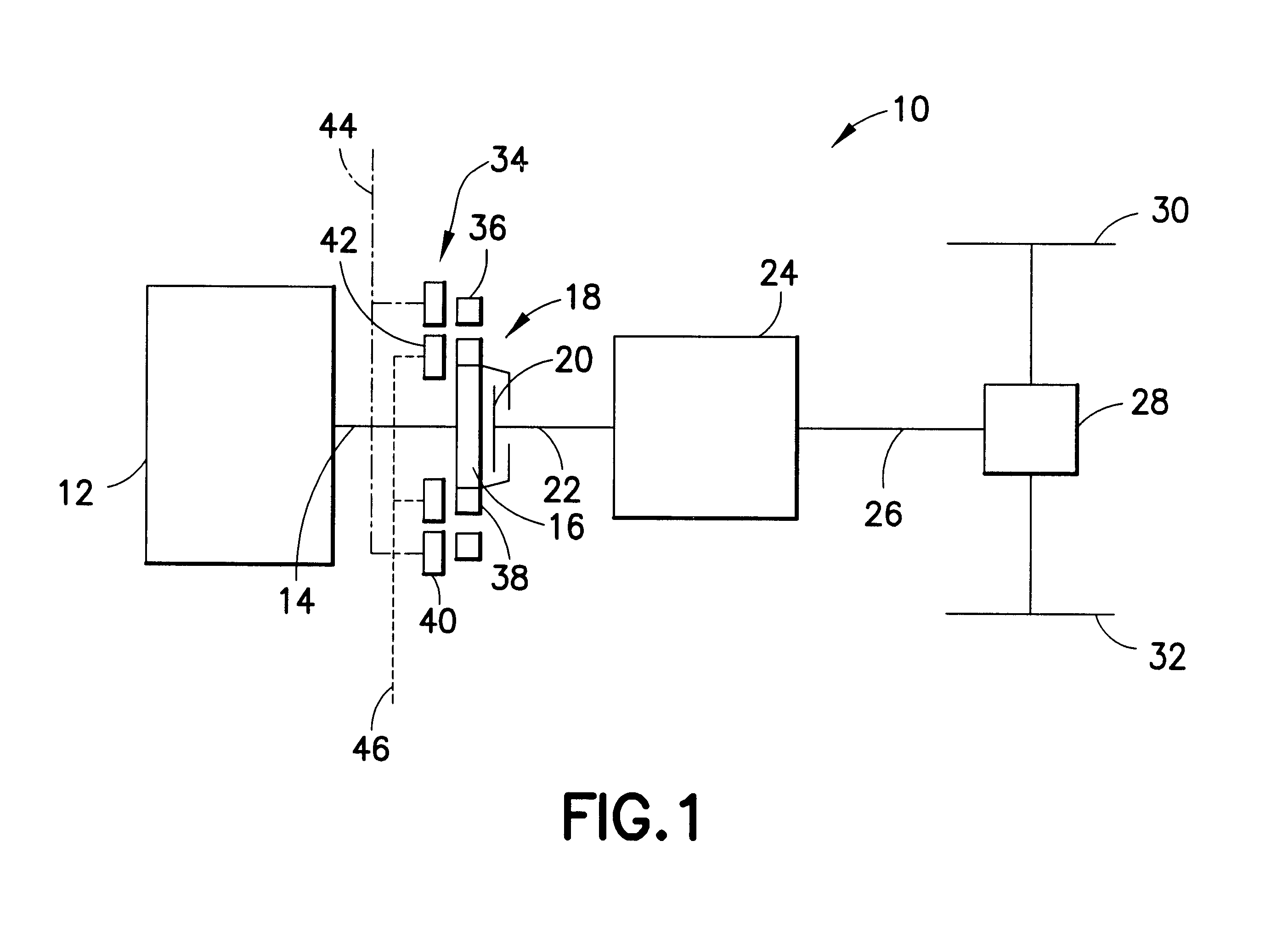
A drive system 10 according to an embodiment of the present invention is illustrated in FIG. 1 which comprises an internal combustion engine 12 as drive unit, a flywheel 16 of a friction clutch 18 coupled to a drive shaft 14, for example, a crankshaft 14 of the internal combustion engine 12. The clutch disk 20 of the friction clutch 18 is connected via a transmission input shaft 22 to a transmission 24 which drives wheels 30, 32 via a transmission output shaft 26 and a differential 28. It may be pointed out that the internal combustion engine 12, the clutch 20, the transmission 24 and various other components may comprise any desired design.

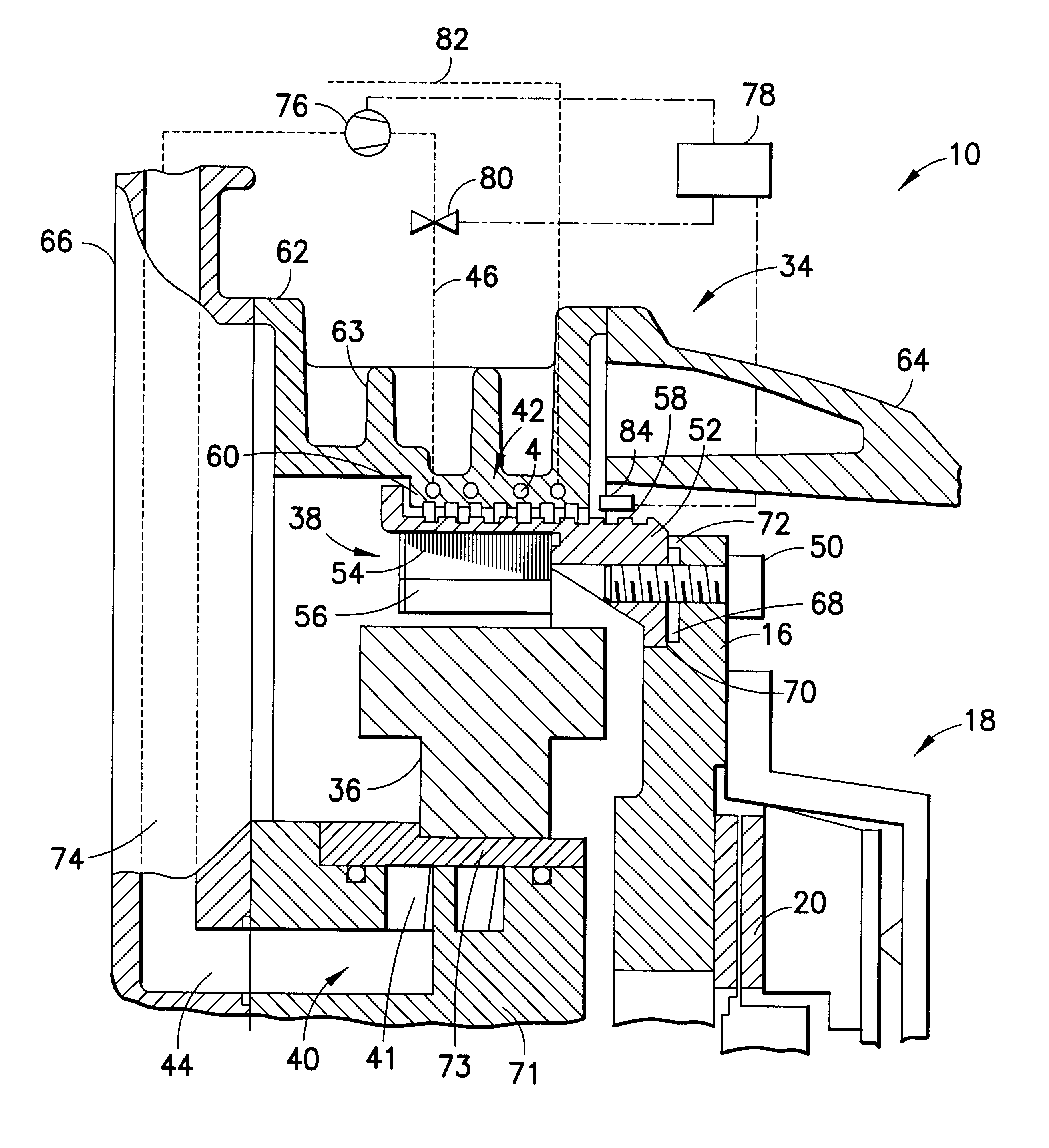
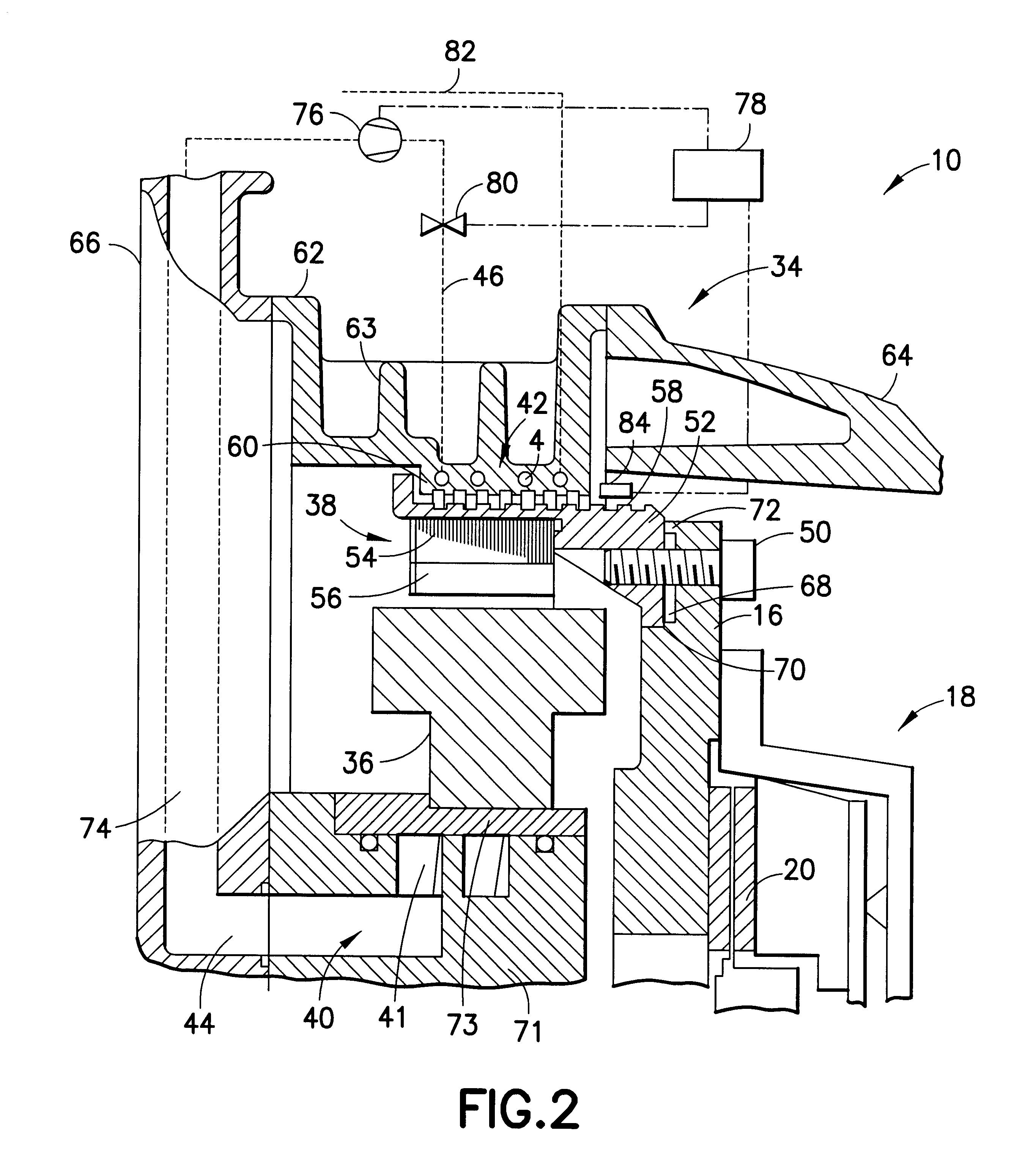
The drive system 10 according to the present invention further comprises an electric machine 34 arranged as a starter / generator arrangement. As described in further detail below with reference to FIG. 2, the electric machine 34 has a stator arrangement 36 with one or more stator windings, which interacts electromagnetically with a rotor arrangeme...


PUM


Abstract

A drive system for a motor vehicle includes a drive shaft and an electric machine operatively connected to the shaft for rotating the shaft and obtaining electric energy during rotation of the drive shaft. The electric machine includes a stator arrangement and a rotor arrangement which can be rotated with the aid of the drive shaft and is operated by permanent magnet. A heat transfer arrangement arranged in the drive system for bringing the rotor arrangement to a desired operating temperature and / or to maintain the desired operating temperature.

Description

1. Field of the InventionThe present invention relates to a drive system for a motor vehicle including an electric machine and a drive shaft, the electric machine being a starter / generator for rotating the drive shaft and obtaining electric energy from a rotating drive shaft, the electric machine having a stator arrangement and a rotor arrangement which can be rotated by the drive shaft and is operated by permanent magnet.2. Description of the Related ArtIn modern drive systems, electric machines are frequently used in so-called starter / generator arrangements to start a drive unit such as, for example, an internal combustion engine, and to generate electric energy when the drive unit is running and the vehicle is in operation for feeding the electrical energy directly into the vehicle network or to charge a battery, i.e., store the energy. However, such electric machines are also used for generating drive energy to supplement or as an alternative to an internal combustion engine. In...

Claims


Application Information

Patent Timeline
Patent Type & Authority Patents(United States)
IPC IPC(8): B60K6/00B60K6/04F01P3/20F02N11/04H02K7/00H02K9/22H02K9/19F01P5/10F01P5/00F01P7/14F01P5/12H02K15/12B60K6/26B60K6/405B60K6/485F02N19/02B60K6/54B60L50/16F02N5/04H02K21/22
CPCB60K6/26B60K6/485B60K6/54F01P3/20F02N11/04H02K7/006H02K9/19H02K9/22B60L3/0061B60L11/14B60L15/20B60K6/405B60L2260/26F01P2005/105F01P2005/125F01P2007/146F01P2050/24F01P2060/185H02K15/125Y02T10/6226Y10S903/906Y10S903/917Y10S903/952B60L2240/36B60L2240/421B60L2240/423B60L2240/425B60L2240/445B60L2240/662Y02T90/16Y02T10/72B60L50/16Y02T10/62Y02T10/64Y02T10/7072B60K2006/268H02K9/227Y02T10/70H02K5/203
Inventor WEIMER, JURGEN
Owner ZF FRIEDRICHSHAFEN AG
Why Eureka
Try Eureka