
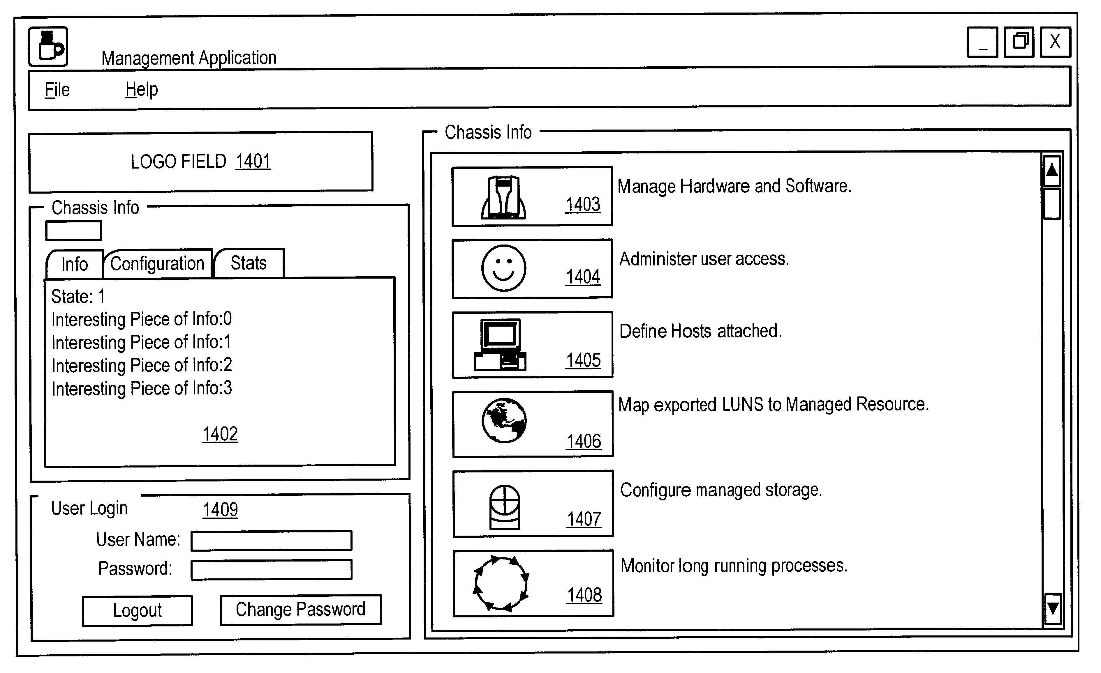
Graphical user interface for configuration of a storage system

Inactive Publication Date: 2003-03-25
DELL PROD LP
View PDF8 Cites 1276 Cited by
  • Summary
  • Abstract
  • Description
  • Claims
  • Application Information

AI Technical Summary

Benefits of technology

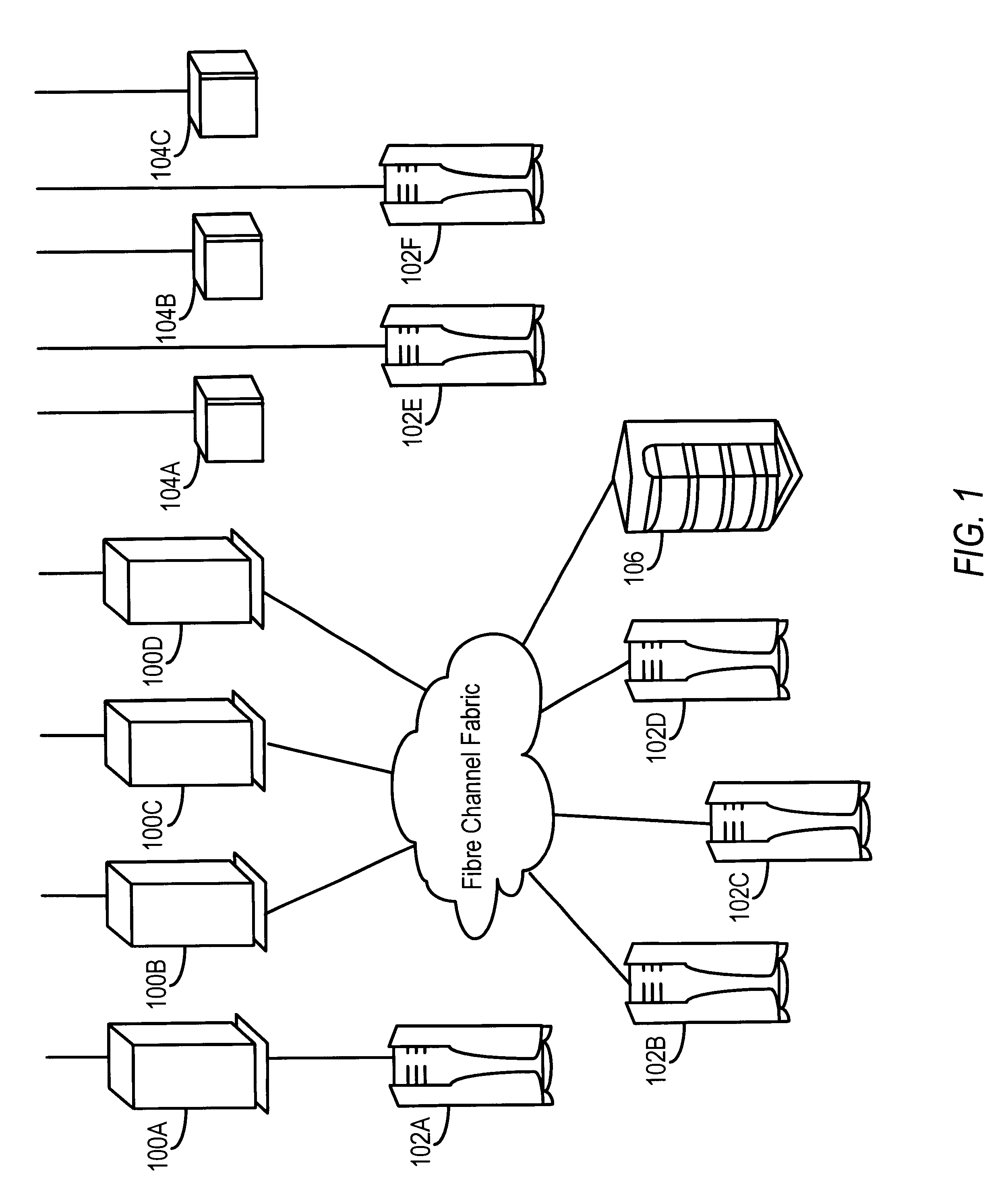
The present invention provides an intelligent storage routing device which manages logical and physical access to a pool of shared storage devices. The device is logically closer to the client server than to the storage devices, and responds to client specific requests for storage transactions which require accessing and sharing a storage area network coupled to the device. The device manages the use of a cache memory to enhance performance. Key functions provided at the device include authentication and access permission logic, virtual circuit mapping, storage mirror functions, and a large non-volatile cache. With these basic functions, many powerful storage management applications can be implemented with existing servers and storage devices, which facilitates the addition of new storage to networks.

Problems solved by technology

Also, if a need arises to move the data from one device to another, in a so-called data migration operation, it is often necessary to block access to the data during the migration process.
Overall, as the complexity and size of storage systems and networks increase, the problems of managing configuration of the users of the data and of the storage systems themselves multiply.

Method used


Image

  • Graphical user interface for configuration of a storage system
  • Graphical user interface for configuration of a storage system
  • Graphical user interface for configuration of a storage system

Examples


Embodiment Construction

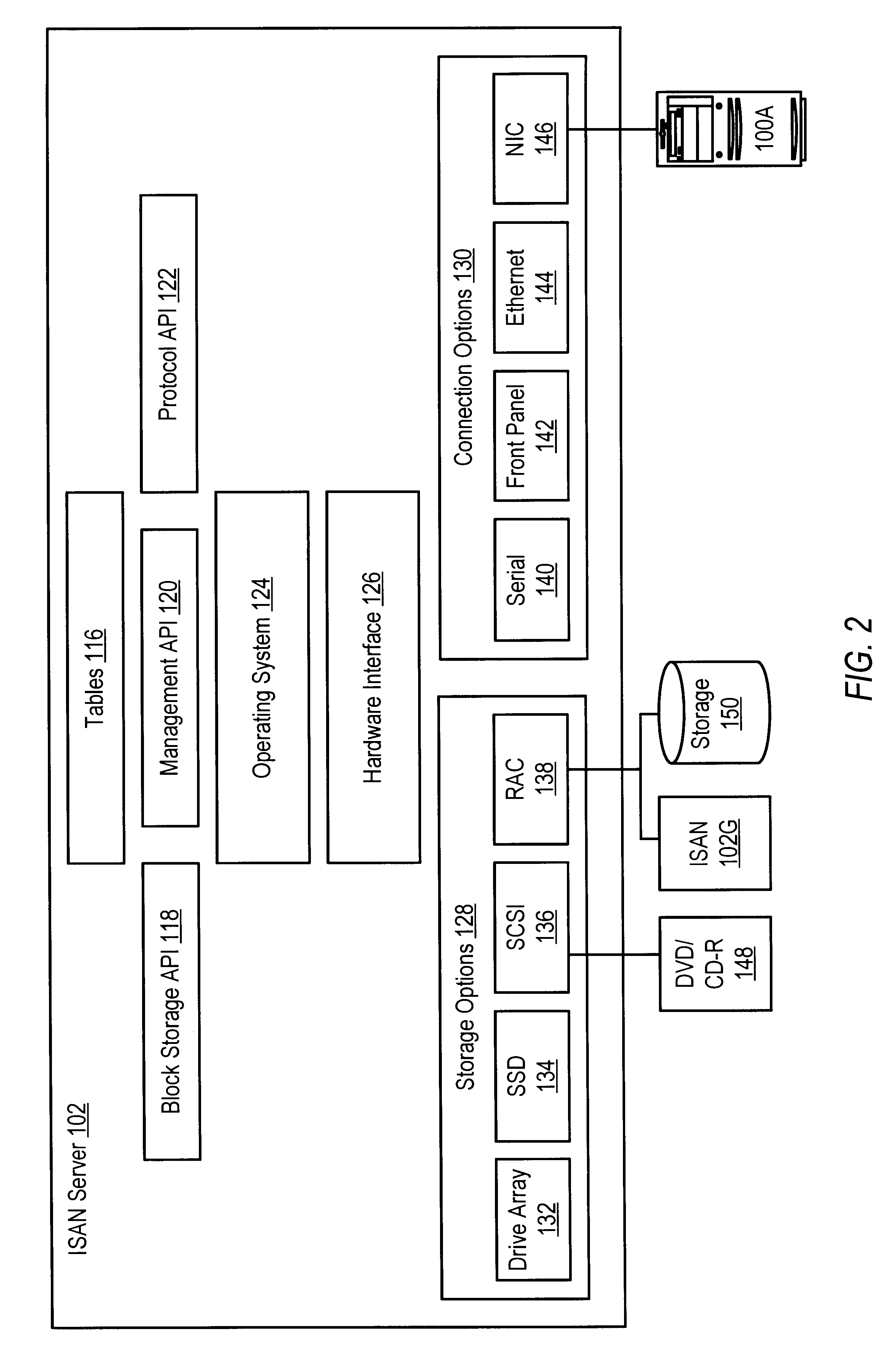
For example, consider a storage transaction that comes over one of the connection options 130 to the ISAN server 102A using the SCSI protocol and designating LUN 2 in the addressing information. Assume that the ISAN server 102A is configured as shown in Tables 1 and 2 for this example.

The connection option such as the network interface 146 over which the storage transaction is received is coupled to a hardware device driver. The hardware device driver receives the storage transaction and depending on the protocol, dispatches it to an appropriate virtual device for handling that protocol.

For example, SCSI storage transactions are sent to a device driver in the SCSI target class. Similarly, IP storage transactions are sent to a device driver in the IP target class. Here, the storage transaction was made using the SCSI communication protocol so it is routed to a SCSI target device driver (DID 500).

The SCSI target device driver further analyzes the request. The first part of the analysi...


PUM


Abstract

A storage server architecture supporting virtual devices and virtual circuits for storing data is provided. The storage server includes a plurality of communication interfaces. A first set of communication interfaces in the plurality is adapted for connection to all kinds of users of data. A second set of communication interfaces in the plurality is adapted for connection to respective devices in a pool of storage devices. Data processing resources in the server are coupled to the plurality of communication interfaces for transferring data among the interfaces. The data processing resources comprise a plurality of driver modules and configurable logic linking driver modules into data paths. Each configured data path acts as a virtual circuit that includes a set of driver modules selected from the plurality of driver modules. A data storage transaction which is received at a communication interface is mapped to one of the configured data paths. A display and a user input device are included with data processing structures to manage images displayed on the display. The images include a first image arranged to prompt a user to input configuration data concerning host systems coupled to one of the plurality of communication interfaces, a second image arranged to prompt a user to input data concerning storage resources coupled to one of the plurality of communication interfaces, and a third image arrange to prompt a user to input data concerning logical addresses used by the host systems to access the storage resources accessible using the server.

Description

1. Field of the InventionThis invention relates to the field of mass storage systems. In particular, the invention relates to the management of storage transactions in, and the configuration of, intelligent storage area networks.2. Description of the Related ArtThe storage of large amounts of data in so-called mass storage systems is becoming a common practice. Mass storage systems typically include storage devices coupled to file servers on data networks. Users in the network communicate with the file servers for access to the data. The file servers are typically to specific storage devices connected via data channels. The data channels are usually implemented with point-to-point communication protocols designed for managing storage transactions.As the amount of storage increases, and the number of file servers in communication networks grows, the concept of a storage area network (SAN) has arisen. Storage area networks connect a number of mass storage systems in a communication ne...

Claims


Application Information

Patent Timeline
IPC IPC(8): G06F3/06G06F3/033G06F3/048
CPCG06F3/0481G06F3/0601G06F17/30126G06F2206/1008G06F2003/0697G06F16/168
Inventor LAGUEUX, JR., RICHARD A.STAVE, JOEL H.YEAMAN, JOHN B.STEVENS, BRIAN E.HIGGINS, ROBERT M.COLLINS, JAMES M.
Owner DELL PROD LP
Learn More