Hollow fiber membrane dehumidification device

Inactive Publication Date: 2003-04-01
NABCO LTD
View PDF18 Cites 35 Cited by
  • Summary
  • Abstract
  • Description
  • Claims
  • Application Information

AI Technical Summary

Problems solved by technology

Since the compressed air that is employed for a drive source for all kinds of devices becomes the cause of early corrosion of the devices

Method used


Image

  • Hollow fiber membrane dehumidification device
  • Hollow fiber membrane dehumidification device
  • Hollow fiber membrane dehumidification device

Examples


Embodiment Construction

There follows below an explanation of the preferred embodiment of the present invention based on FIG. 1 to FIG. 4.

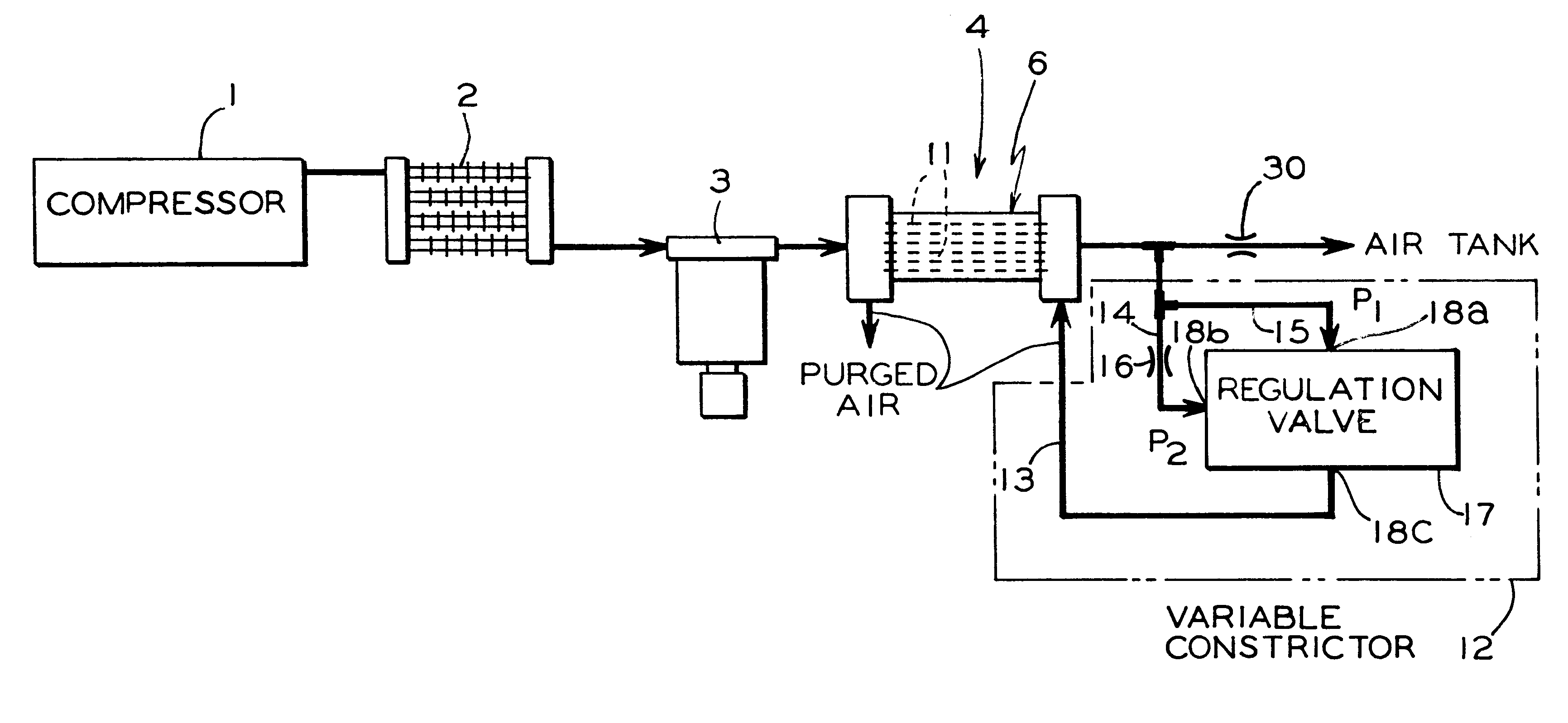
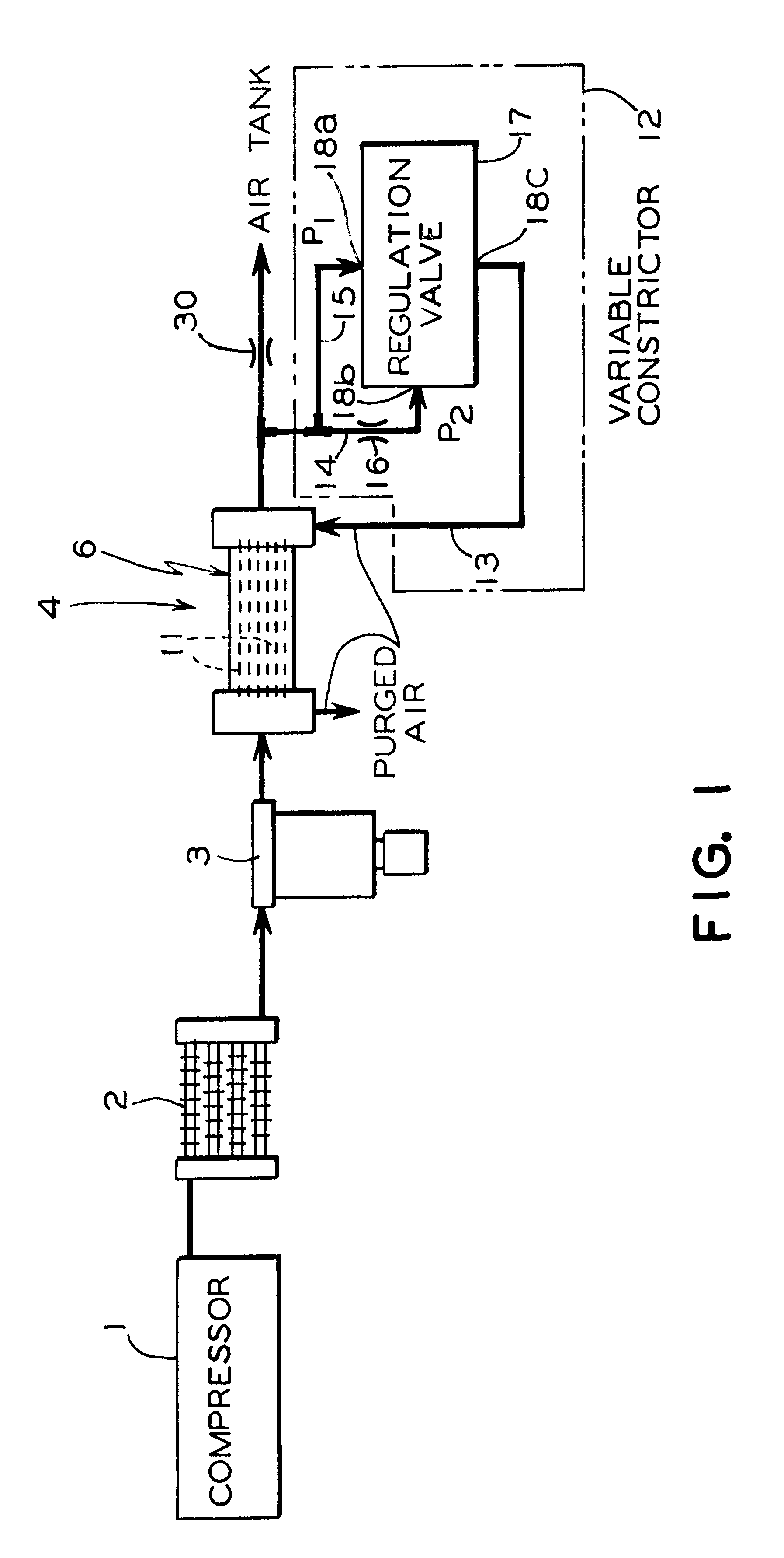
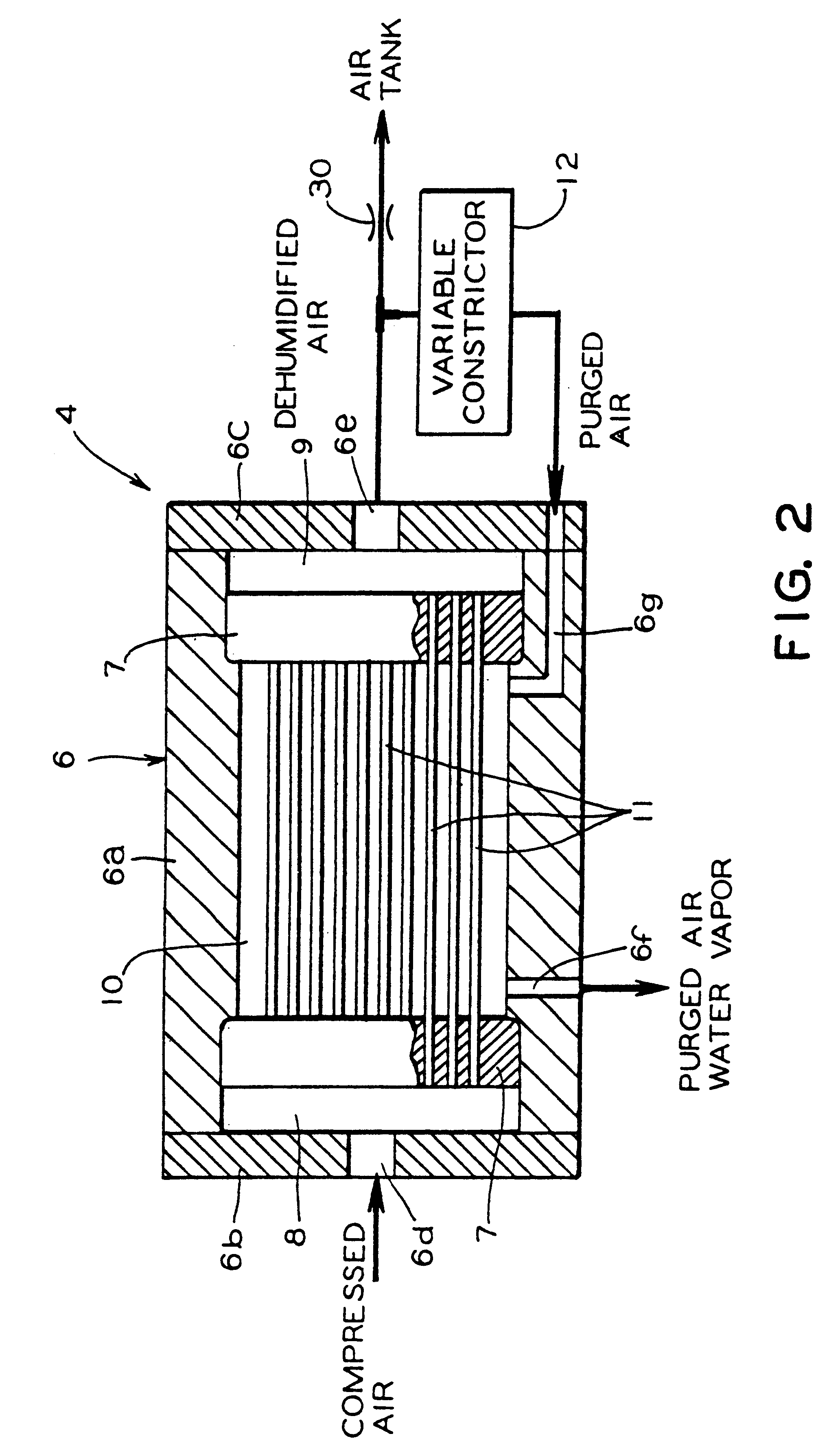
The hollow fiber membrane type dehumidification device for the embodiment of the present invention is employed by incorporating it into the air source system of such things as railway cars, large automobiles, ships, and other machine equipment. This air source system possesses, in order from the upper stage to the rear stage, as shown in FIG. 1, (a) an air compressor (1) that is a compressor employing the atmosphere as compressed air; (b) an aftercooler (2) that dehumidifies the compressed air by cooling it; (c) a separator (3) that eliminates the water droplets and dust and oil mist in the compressed air; (d) a hollow fiber membrane type dehumidification device (4) that dehumidifies the compressed air and makes it into dehumidified air; (e) a second orifice (30) that controls the flow of dehumidified air; and (f) an air tank that accumulates under pressure the dehumidif...


PUM


Abstract

A hollow fiber membrane dehumidification device that possess hollow fiber membranes that cause the compressed air supplied from one end to the interior to flow through and at the same time discharge moisture in the compressed air to the outside, and by so doing exhausts the compressed air to the other end as dehumidified air. There is a reflux route that causes a portion of the dehumidified air exhausted from the hollow fiber membranes to flow back to the outside of the hollow fiber membranes as purged air and a variable restrictor that is provided on the reflux route that increases or decreases the opening-closing volume in accordance with the increase or the decrease of the pressure of the compressed air that flows through the interior of the hollow membranes.

Description

TECHNICAL FIELD TO WHICH THE INVENTION PERTAINSThe present invention relates to a hollow fiber membrane dehumidification device that dehumidifies compressed air by means of hollow fiber membranes.1. Prior ArtSince the compressed air that is employed for a drive source for all kinds of devices becomes the cause of early corrosion of the devices when it contains a large amount of moisture ordinarily it is employed as the drive source after it has been dehumidified by a dehumidifier. A freezing type and an adsorption type are generally adopted for this kind of dehumidification device, but in recent years hollow fiber membrane type dehumidification devices have attracted attention based on the facts that they have been miniaturized, made lighter, and had their maintenance operations simplified.Previously the above-mentioned hollow fiber membrane dehumidification devices involved as shown in FIG. 5 the positioning of multiple hollow fiber membranes (52) in a housing chamber (53) inside a...

Claims


Application Information

Patent Timeline
IPC IPC(8): B01D53/26B01D53/22B01D63/02
CPCB01D53/268B01D63/02B01D2319/04B01D2313/22B01D2313/18
Inventor HACHIMAKI, TAKESHI
Owner NABCO LTD
Why Eureka
Try Eureka