Method of and apparatus for fluid sealing, while electrically contacting, wet-processed workpieces

a technology for fluid sealing and workpieces, applied in sealing devices, mechanical devices, manufacturing tools, etc., can solve the problems of difficult fitting into such a narrow region around the workpiece periphery, the surface deposition of electrically conductive gaskets is subject to deposition, and the effect of reducing the thickness of the film

Inactive Publication Date: 2003-04-01
HERCULES TECH GROWTH CAPITAL
View PDF3 Cites 94 Cited by
  • Summary
  • Abstract
  • Description
  • Claims
  • Application Information

AI Technical Summary

Benefits of technology

Preferred and best mode designs and details are later explained.

Problems solved by technology

Making a reliable and uniform electrical contact to the edge of a workpiece and, at the same time sealing the edge against fluid invasion is a recognized and difficult problem in the art of high precision electrodeposition on workpieces such as semiconductor wafers and the like.
During such electrodeposition, if the electrical contact to the workpiece is not uniform or if the contact has high resistance to current flow, the desired uniform deposited film may not be achieved.
The use of a separate seal and frame and contact compliance means as proposed by Brogden, however, is difficult to fit into such a narrow region around a workpiece periphery.
Unfortunately, the electrically conductive gasket, however, is subject to deposition on the surface, requiring undescribed frequent system maintenance.
If the resilient sealing member is elastic enough to provide sufficient microscopic deformation of the fluid sealing member to mate with the microscopic surface the irregularities of the workpiece, then the sealing member is not mechanically stiff enough to provide sufficient force at the workpiece surface to cause the requisite deformation, and hence the resulting fluid seal is imperfect.
For some applications, however, this means requires too much space both in front of and behind the workpiece.

Method used


Image

  • Method of and apparatus for fluid sealing, while electrically contacting, wet-processed workpieces
  • Method of and apparatus for fluid sealing, while electrically contacting, wet-processed workpieces
  • Method of and apparatus for fluid sealing, while electrically contacting, wet-processed workpieces

Examples


Embodiment Construction

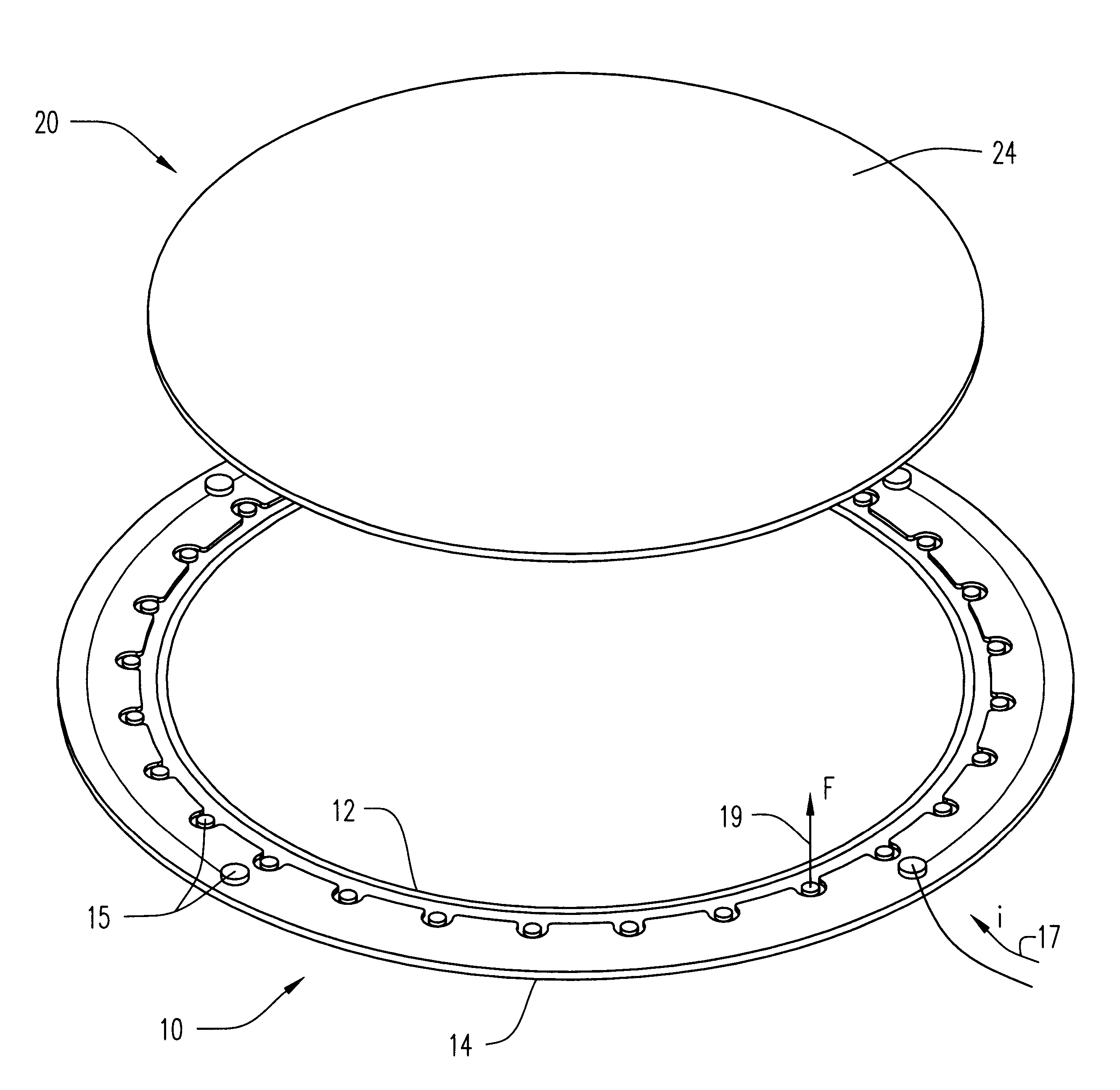
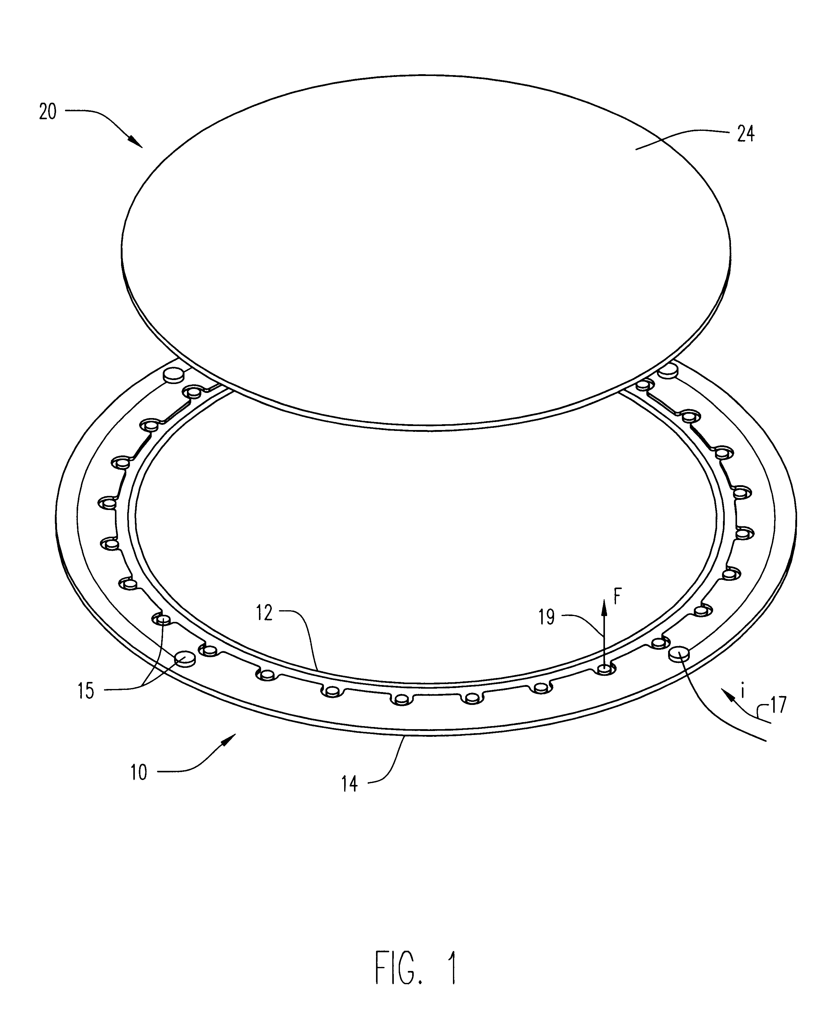
Referring to FIG. 1, the invention, as applied to the before-mentioned illustrative and important field of electrodeposition of circular wafers and the like, comprises a sealing ring assembly 10 primarily comprised of a flexure assembly 12 that is molded into a sealing element 14. The sealing ring assembly 10 is configured completely to surround the wafer workpiece 20. Most commonly, both the workpiece 20 and the sealing ring assembly 10 will be of circular or rectangular shape. As earlier mentioned, a useful application of the invention is for processing semiconductor wafers, which are circular. That circular shape is illustratively shown in the drawings; it being noted, however, as before explained, that the invention is also applicable to rectangular workpieces such as printed circuit boards, package substrate panels, or flat panel displays or the like. One or more connection rods 15 are shown attached to the flexure assembly 12, providing a path through which electrical current,...


PUM

PropertyMeasurementUnit
perimeteraaaaaaaaaa
flexibleaaaaaaaaaa
uniform electricalaaaaaaaaaa

Abstract

A method and apparatus for fluid sealing the underside of a workpiece, such as a semiconductor wafer and the like, during wet-processing such as electrodeposition and the like, employing an elastomeric encased ring of flexible fingers against which the periphery of the workpiece underside is forced to deflect the fingers downwardly and engage a peripheral sealing bead against the underside periphery of the workpiece; and where electrical contact with the workpiece is desired, resiliently engaging electrical contact tips protruding through peripheral openings in the elastomeric covering within the sealing ring, with the underside periphery of the workpiece.

Description

The present invention relates generally to workpiece wet processing, such as electrodeposition, electro-etching, and electroless deposition and the like; being particularly, though not exclusively, concerned with electrodeposition onto substantially planar thin workpieces, such as silicon wafers and the like, and in a manner suitable for high-volume manufacturing. Specifically, the invention is directed to apparatus for reproducibly making a fluid seal to the outer perimeter of a face of such a workpiece, and in a manner conducive for simultaneously making uniform electrical contact along the workpiece perimeter.Electroplating and electroless plating are two major forms of wet chemistry deposition that are used in manufacturing for the application of copper, gold, lead-tin, indium-tin, nickel-iron, nickel and other types of metals or alloys of metals to workpiece surfaces such as semiconductor wafers, printed circuit board substrates, thin-film heads, and flat panel displays and the...

Claims


Application Information

Patent Timeline
Patent Type & Authority Patents(United States)
IPC IPC(8): C25D7/12C25D17/06H01L21/00
CPCC25D17/06C25D17/004C25D17/001H01L21/67126
Inventor KEIGLER, ARTHUR
Owner HERCULES TECH GROWTH CAPITAL
Why Eureka
Try Eureka