Drive device

a technology of drive device and drive shaft, which is applied in the direction of clamps, couplings, mechanical equipment, etc., can solve the problems of still substantial wear problems, and achieve the effect of reducing the rate of wear and the need for servicing, and high drive for

Inactive Publication Date: 2003-04-08
FESTO AG & CO KG
View PDF15 Cites 61 Cited by
  • Summary
  • Abstract
  • Description
  • Claims
  • Application Information

AI Technical Summary

Benefits of technology

One object of the invention is to create a drive device with which high drive forces may be transmitted while reducing the rate of wear and the need for servicing.
It is in this manner that an electro-hydraulic drive device is created, in which owing to a closed hydraulic circuit the leakage problem may be extremely readily gotten under control and the special control by the electric motor activated hydraulic pump means that no expensive servo valves are required to operate the hydraulic drive in the desired manner. Dispensing with servo valves does in this respect offer the advantage as well that there are only relatively modest requirements for servicing of the hydraulic medium, this meaning that servicing of the equipment is extremely economic. The activation of the hydraulic drive is preferably only made dependent on the operational state of the hydraulic pump and may for example be controlled in a vary simple manner for instance by switching on and off and presetting a certain speed of rotation of the pump.
Further advantageous developments of the invention are defined in the claims. Different actuating pressures required during operation of the hydraulic drive may be conveniently preset in a manner dependent on the speed of rotation of the hydraulic pump. Thus loads can be accelerated or retarded without having to have recourse to an intermediately placed servo valve means, which influences the flow cross section. In this respect use is preferably made of suitable setting means, which may be controlled or regulated by way of a variable preset of the speed of rotation of the electric motor determining the hydraulic pump's speed of rotation. A possibility may also be provided for setting speed of rotation change functions in order to fashion the acceleration and retardation of a load to the moved by the hydraulic drive in a smooth manner and to avoid jerky motion.
The two hydraulic circuits of the drive device preferably contain a respective overridable check valve, which normally permits fluid flow from the hydraulic pump to the hydraulic drive and prevents it in the opposite direction, each check valve being able to be overridden by the pressure maintained in the respectively other hydraulic circuit by the hydraulic pump in order to render possible fluid flow from the hydraulic drive back to the hydraulic pump. It is in this manner that any desired intermediate positions of the drive piston may be maintained without the constant supply of energy, because the hydraulic medium is trapped by the check valves in the working chambers when the hydraulic pump is not activated. If on the contrary the hydraulic pump is activated, the pressure then established in the one hydraulic circuit overrides the check valve, located in the other hydraulic circuit and accordingly renders possible free movement of the working piston.
A further particularly advantageous design of the drive device is one in which at least one and preferably both hydraulic circuits contain a biasing valve, which normally shuts off the fluid connection from the associated working chamber to the hydraulic pump and only opens it, when and as long as a predetermined opening pressure is established. Thus the biasing valve is responsible for biasing of the hydraulic medium located in the output working chamber, which medium can not be immediately displaced, when there is an increase in pressure in the input chamber. It is only when the increase in pressure in the input working chamber is so strong that the pressure building up in the output working chamber reaches the minimum pressure, termed the opening pressure, that the previously entering hydraulic medium may leave. Since the pressure obtaining in the output working chamber then however produces a constant opposing opposite force to the desired direction of movement of the drive piston, the drive piston may be extremely quickly and accurately retarded even in the case of a very dynamic movement simply by varying the operational state of the hydraulic pump to change the pressure applied on the input side. Therefore even without servo controlled hydraulic valves extremely exact positioning of the drive piston or, respectively, of a force or power output connection member coupled therewith can be achieved even at high speeds of operation.

Problems solved by technology

While in the case of pneumatic drives design must be generally technically complex owing to the compressibility of the operating medium if accuracy of positioning and slow motion are to be possible, with hydraulic drives the principal problem is that of leakage and the large amount of upkeep work needed to ensure reliable hose connections and maintaining a high quality hydraulic medium in the system.
However there is still a substantial wear problem here, more particularly when transmitting heavy setting forces.

Method used


Image

  • Drive device
  • Drive device
  • Drive device

Examples


Embodiment Construction

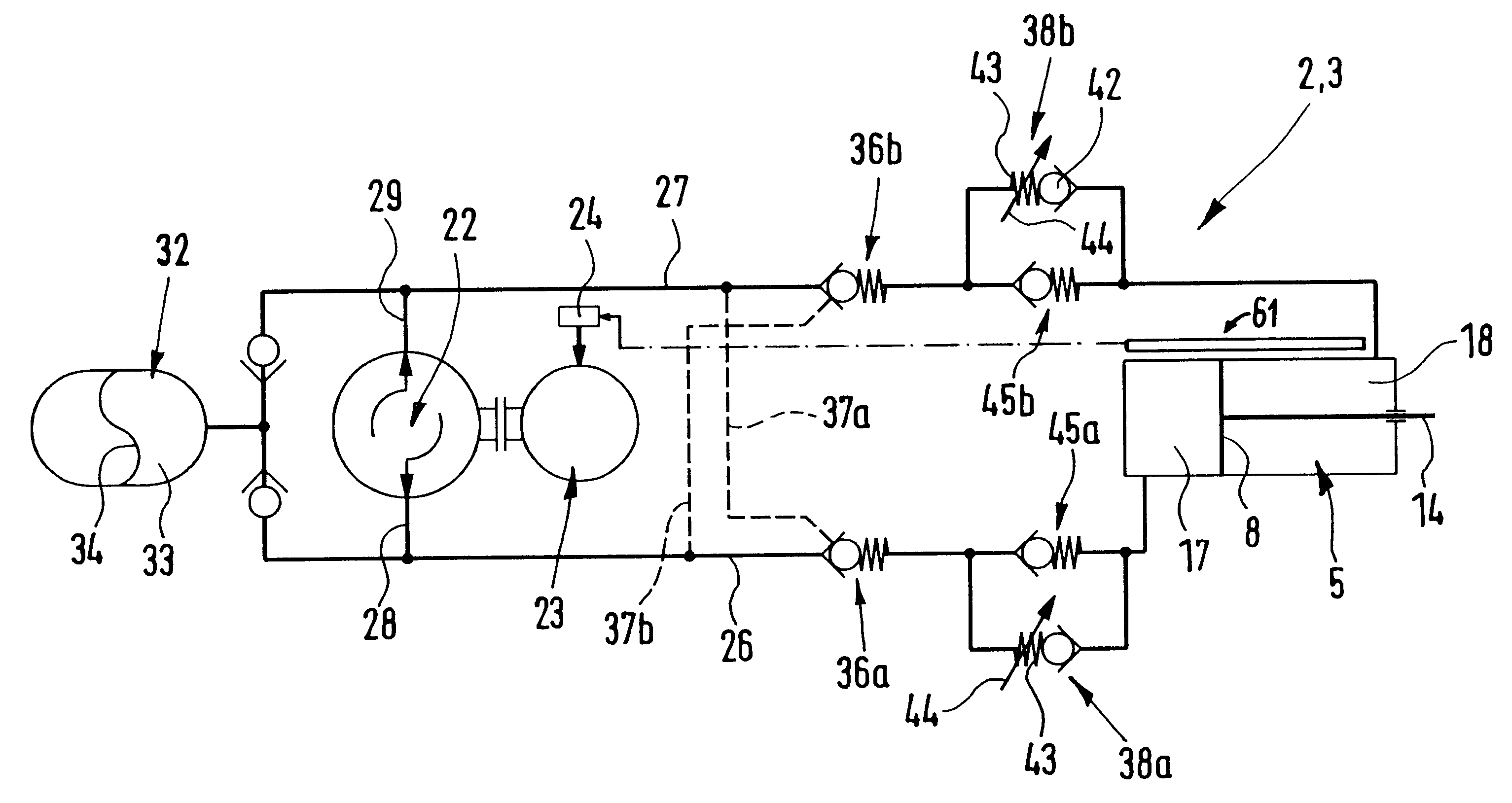
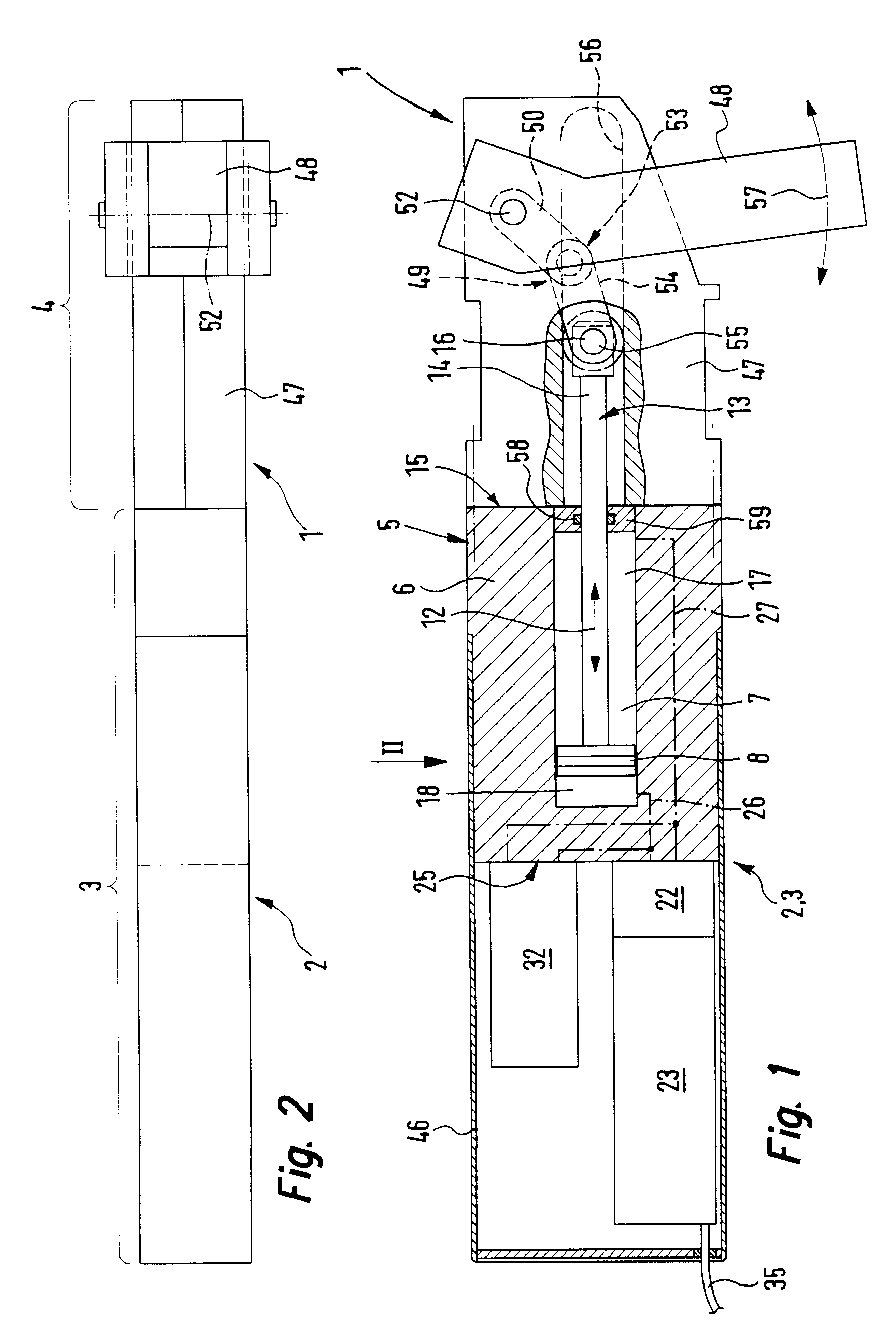
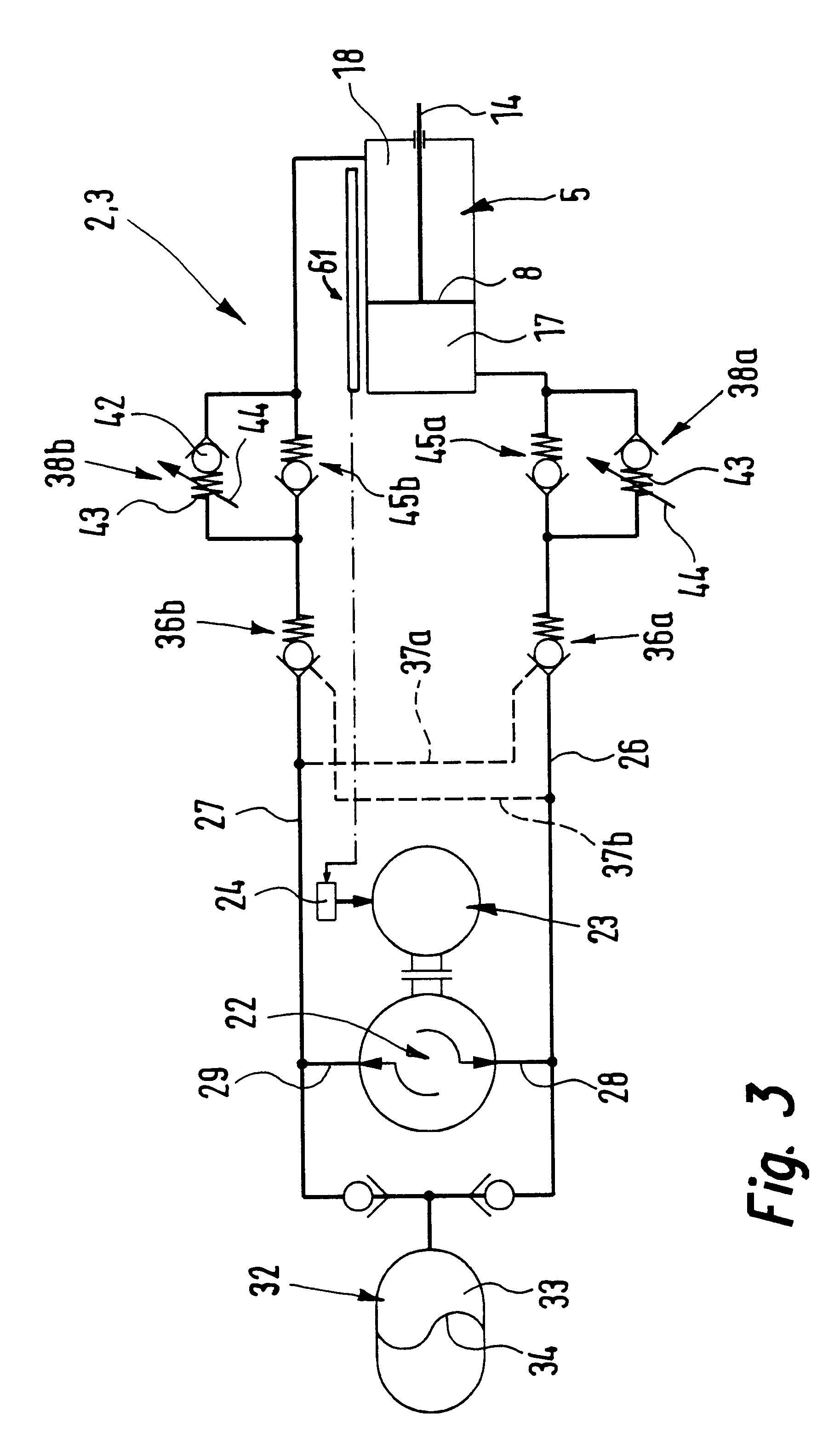
FIGS. 1 and 2 depict a clamping device 1 operating on the toggle lever principle and whose principal components are a drive device 2 which can thus be termed a drive unit 3 in the form of an assembly and a clamping unit 4 permanently connected with the drive unit 3. The details of the circuitry of the drive device 2 and, respectively, of the drive unit 3 are only indicated diagrammatically in FIG. 1, whereas FIG. 3 is a more detailed circuit diagram of a particularly preferred design.

The drive device 2 comprises a hydraulic drive 5 adapted to be actuated by a hydraulic medium and which in the working example is designed in the form of a linear drive, but which in another field of application of the drive device 2 could be in the form of a rotary drive, for example.

The hydraulic drive 5 possesses a housing 6, in which an elongated piston receiving space 7 is located, same containing a drive piston 8. This piston 8 is a component of an output drive unit 13 able to slide in a driving m...


PUM


Abstract

A drive device comprising a closed hydraulic circuit which has a hydraulic drive adapted to be actuated by hydraulic medium and has a hydraulic pump responsible for the supply and removal of the hydraulic medium to and from the hydraulic drive. For the operation of the hydraulic pump an electric motor is provided. The activation of the hydraulic drive is controlled by the operational state of the hydraulic pump.

Description

The invention relates to the drive device art and more specifically to drive devices having a drive to be activated by the supply of energy and which deliver drive power.THE PRIOR ART.Such a drive device is for example disclosed in the German utility model 29,903,825.4, where it is described as a component of a toggle clamping device. It comprises a pneumatic drive able to be operated by compressed air with its associated electrically actuated control valves in order to set the direction of driving of the pneumatic drive. As an alternative a hydraulic drive would be possible as well which is connected with electrically actuated servo valves in order to influence the state of the drive. While in the case of pneumatic drives design must be generally technically complex owing to the compressibility of the operating medium if accuracy of positioning and slow motion are to be possible, with hydraulic drives the principal problem is that of leakage and the large amount of upkeep work need...

Claims


Application Information

Patent Timeline
Patent Type & Authority Patents(United States)
IPC IPC(8): B25B5/06B25B5/00B25B5/12F15B11/00F15B7/00F15B9/04F15B9/00F15B15/18F15B15/00B25B11/00
CPCB25B5/061F15B7/006F15B9/04F15B11/003F15B15/18B25B5/122F15B2211/625F15B2211/20515F15B2211/20561F15B2211/27F15B2211/3051F15B2211/3144F15B2211/31576F15B2211/329F15B2211/5059F15B2211/513F15B2211/5153F15B2211/528F15B2211/56F15B2211/6336F15B2211/6651
Inventor MUSCHONG, GUNTHERSTOLL, KURT
Owner FESTO AG & CO KG
Why Eureka
Try Eureka