Embedded interferometer for reference-mirror calibration of interferometric microscope

a reference mirror and interferometer technology, applied in the field of interferometry, can solve the problems of vibration, wear, and different results of different operators, and achieve the effect of easy and economical implementation

Inactive Publication Date: 2003-04-08
BRUKER NANO INC
View PDF2 Cites 129 Cited by
  • Summary
  • Abstract
  • Description
  • Claims
  • Application Information

AI Technical Summary

Benefits of technology

A final object is a procedure that can be implemented easily and economically according to the above stated criteria.
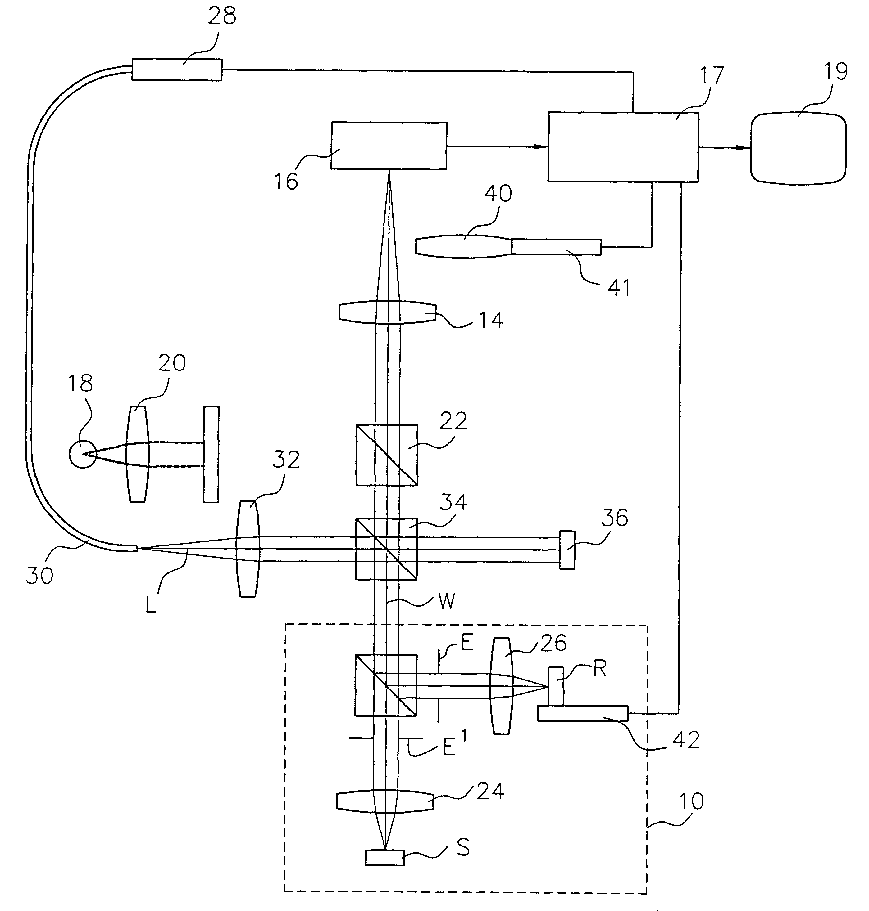
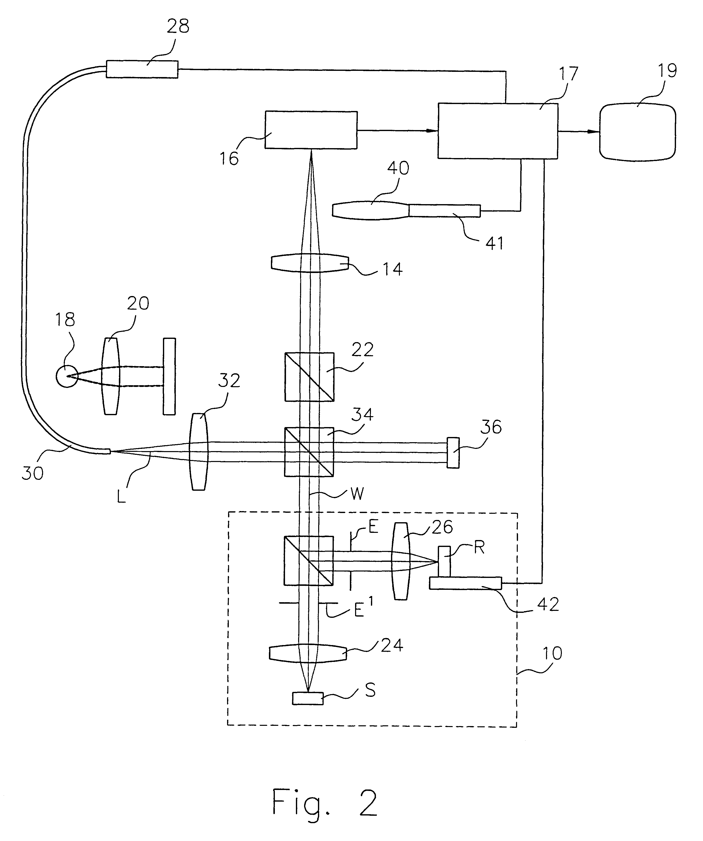
Therefore, according to these and other objects, the present invention consists of incorporating a laser interfero-meter into an interference microscope to precisely determine the in-focus position of the microscope objectives reference mirror. A collimated laser beam is introduced into the microscope system and split into two beams directed toward a special calibration reference surface and the interference objective. The light reflected from the special reference surface is returned to the camera. The light into the interference objective is focused onto the reference mirror and returned to the camera. When the reference mirror is in focus, the returned beam is collimated; if the mirror is on either side of focus, the beam is either converging or diverging. Accordingly, the interferogram produced at the camera reflects the in-focus to out-of-focus condition of the

Problems solved by technology

However, due to practical limitations on stability, it often must be left adjustable and set by the user during setup procedures.
Such manual setting of the reference-mirror focus suffers from two distinct limitations.
First, it is based on an operator's visual observation of best focus, which is necessarily approximate because of the inability of the hu

Method used


Image

  • Embedded interferometer for reference-mirror calibration of interferometric microscope
  • Embedded interferometer for reference-mirror calibration of interferometric microscope
  • Embedded interferometer for reference-mirror calibration of interferometric microscope

Examples


embodiment 50

Furthermore, in accordance with the general concept of the invention, it is understood that it can be implemented in various alternative optical embodiments that make it possible to determine the shape of the return wavefront from the reference mirror R. As would be understood by those skilled in the art, this can be accomplished even without a calibration reference surface 36 by interfering the return wavefront RB with a separate collimated beam of light (which may result from splitting the laser beam L, as in the case illustrated for the preferred embodiment of FIG. 5) in the optical path to the sensor array 16, or equivalently by passing the return wavefront through a shearing interferometer, such as a shear plate, to produce two interfering beams. For example, FIG. 10 shows schematically the invention wherein two laser beams L and L' are produced by a fiber-optic splitter 52 (or, equivalently, by two separate compatible lasers); the first beam L is directed toward the reference ...

embodiment 60

Another embodiment 60 of the invention is implemented by splitting the single beam L out of the optical fiber 30 in a splitter 62 and routing it directly to the imaging array 16 using two additional reflective surfaces 64 and 66, as illustrated in FIG. 11.

An equivalent implementation 70 using a single light beam L and a shear plate is shown in FIG. 12. The return wavefront RB produced by the laser beam L is diverted in a splitter 72, re-directed by folding mirrors 74,76, passed through a shear plate 78, and directed to the array 16. It is well known in the art that the interference of the waves emerging from the shear plate will produce parallel fringes having orientation depending on whether the incident wavefront is plane or spherical (i.e., diverging or converging). Therefore, the direction of the fringes in an interferogram of the light detected by the sensor 16 in relation to their in-focus position enables the immediate identification of the out-of-focus condition of the mirro...

embodiment 80

It is also noted that the return wavefront RB in all embodiments illustrated in the figures is directed to the sensor array 16 of the interference microscope in order to utilize hardware already available to perform interferometric measurements. On the other hand, the concept of the invention could be carried out in equivalent fashion by adding additional detector hardware 16' solely for the purpose of calibration, as illustrated schematically with FIG. 13 with reference to the shear-plate implementation. It is also understood that the shape of the return wavefront may be determined by various other tests known in the art, such as, without limitation, the knife-edge, wire, and screen tests.


PUM


Abstract

A laser interferometer is embedded into an interference microscope to precisely determine the in-focus position of the microscope objective's reference mirror. A collimated laser beam is introduced into the microscope system and split into two beams directed toward a calibration reference surface and the interference objective. The light reflected from the calibration reference surface is returned to the camera. The light into the interference objective is focused onto the reference mirror and returned to the camera. For the purpose of calibration, the two beams are combined at the camera to produce interference fringes. When the reference mirror is in focus, the returned beam is collimated; if the mirror is on either side of focus, the beam is either converging or diverging. Accordingly, the interferogram produced at the camera reflects the in-focus or out-of-focus condition of the reference mirror. The curvature of the wavefront returned from the reference mirror is determined electronically by analyzing the interference fringes produced with the beam returned from the calibration reference surface. By minimizing the curvature of the reference-mirror wavefront as the mirror is translated along the optical path, the reference mirror can be focused with an accuracy greater than possible by visual observation. Furthermore, by automating the focusing system with a precise translation mechanism driven by closed-loop control, operator-to-operator variations are completely eliminated.

Description

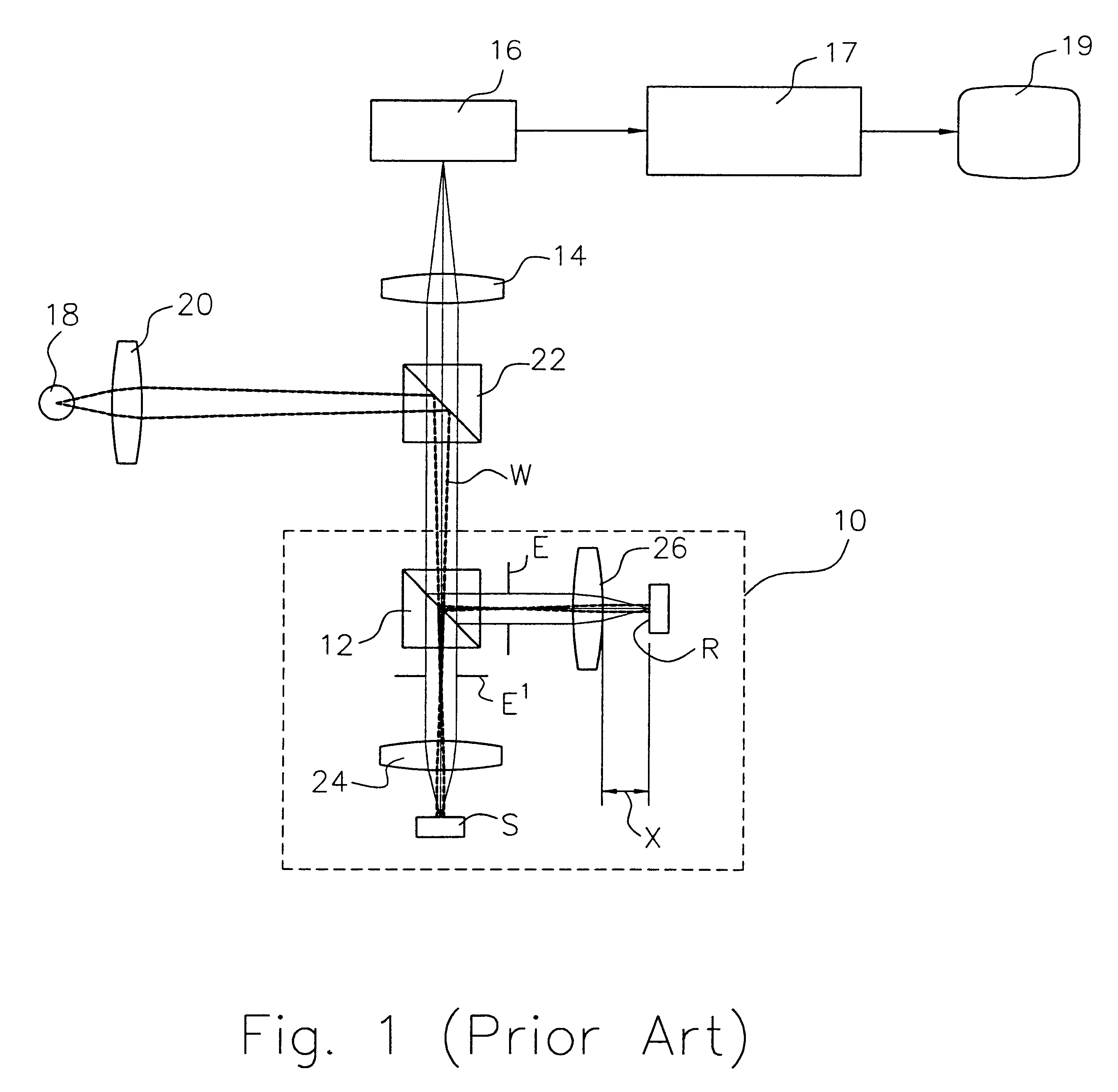
1. Field of the InventionThis invention is related in general to the field of interferometry and, in particular, to a method and apparatus for optimizing the focal-point calibration of an interferometric microscope.2. Description of the Related ArtMicroscope objectives are commonly used in interferometric devices for focusing a beam of light on a sample surface and a reference surface to produce interference fringes representative of the optical path difference (OPD) between the test and reference path. As illustrated in simple schematic form in FIG. 1, a typical interferometric microscope 10 consists of a microscope objective focused on a test surface S and incorporating an interferometer. The interferometer, shown in Linnik configuration for illustration, comprises a beam splitter 12 and a reference mirror R such that the light beam W directed to the sample surface S is split and also directed to the reference mirror. As is well understood by those skilled in the art, the light be...

Claims


Application Information

Patent Timeline
IPC IPC(8): G01B9/02
CPCG01B9/04G02B21/14G02B21/247G01B9/02072G01B9/02042G01B9/02043G01B9/02063G01B2290/60
Inventor AZIZ, DAVID J.GUENTHER, BRYAN W.
Owner BRUKER NANO INC
Why Eureka
Try Eureka