Electronic device

Inactive Publication Date: 2003-04-08
FUJITSU LTD
View PDF21 Cites 13 Cited by
  • Summary
  • Abstract
  • Description
  • Claims
  • Application Information

AI Technical Summary

Benefits of technology

The first embodiment of the present invention provides an electronic device comprising an outside panel which includes a plurality of independent spaces for thermal insulation regularly arranged in the outside panel in parallel to each other. Temperature of the outer surface of the outside panel is decreased by the heat insulating action of the spaces. Therefore, the apparent temperature of the outside panel is decreased.
The second embodiment of the present invention provides an electronic device comprising an outside panel which includes a plurality of ducts arranged in the outside panel in parallel to each other, wherein the plurality of ducts are partitioned from each other by partition walls. The temperature of the outside panel is substantially decreased by the action of the ducts. Therefore, the outer surface temperature (apparent temperature) is decreased.
The third embodiment of the present invention provides an electronic device comprising an outside panel which includes a plurality of protrusions arranged on an external surface of the outside panel, wherein a forward end portion of each protrusion is composed of a thermally insulating section made of thermally insulating material. Due to the above arrangement, a contact area of an operator with respect to the outside panel is substantially decreased. Also, due to the existence of the heat insulating sections arranged at the end portions of the protrusions, the apparent temperature of the outside panel is decreased.
The fourth embodiment of the present invention provides an electronic device comprising an outside panel, wherein a high temperature zone is provided in a region in the device corresponding to a predetermined portion of the outside panel which is difficult for an operator to touch, and parts generating a large quantity of heat are collected and mounted in the high temperature zone. The temperature of a region in the device corresponding to a portion of the outside panel which can be easily touched by an operator is relatively decreased. Therefore, the outer surface temperature (apparent temperature) of a portion of the outside panel, which is easily contacted by the operator, is decreased.
The fifth embodiment of the present invention provides an electronic device comprising an outside panel, wherein a thermal insulating layer is formed on an outer surface of the outside panel. Since the heat insulating layer is provided, the apparent temperature with respect to the outside panel is decreased.
The sixth embodiment of the present invention provides an electronic device comprising: an outside panel; and a pressure generating unit for keeping the inside of the device at high pressure, wherein the outside panel is provided with a plurality of holes, and air inside of the device is jetted out from the holes. When the air is jetted out from the holes, the outer surface temperature of the outside panel is decreased.

Problems solved by technology

However, when the structure disclosed in the above patent publication is adopted, it is estimated that the temperature on the surface (heat radiating surface) of the casing will become very high.
In this case, when an operator touches the surface of the casing with his hand or with a portion of his body, there is a possibility that the operator may be hurt.
However, when a position, at which the heat emitting section is arranged, is restricted, it becomes difficult to emit heat effectively when the heating amount is increased.

Method used


Image

  • Electronic device
  • Electronic device
  • Electronic device

Examples


first embodiment

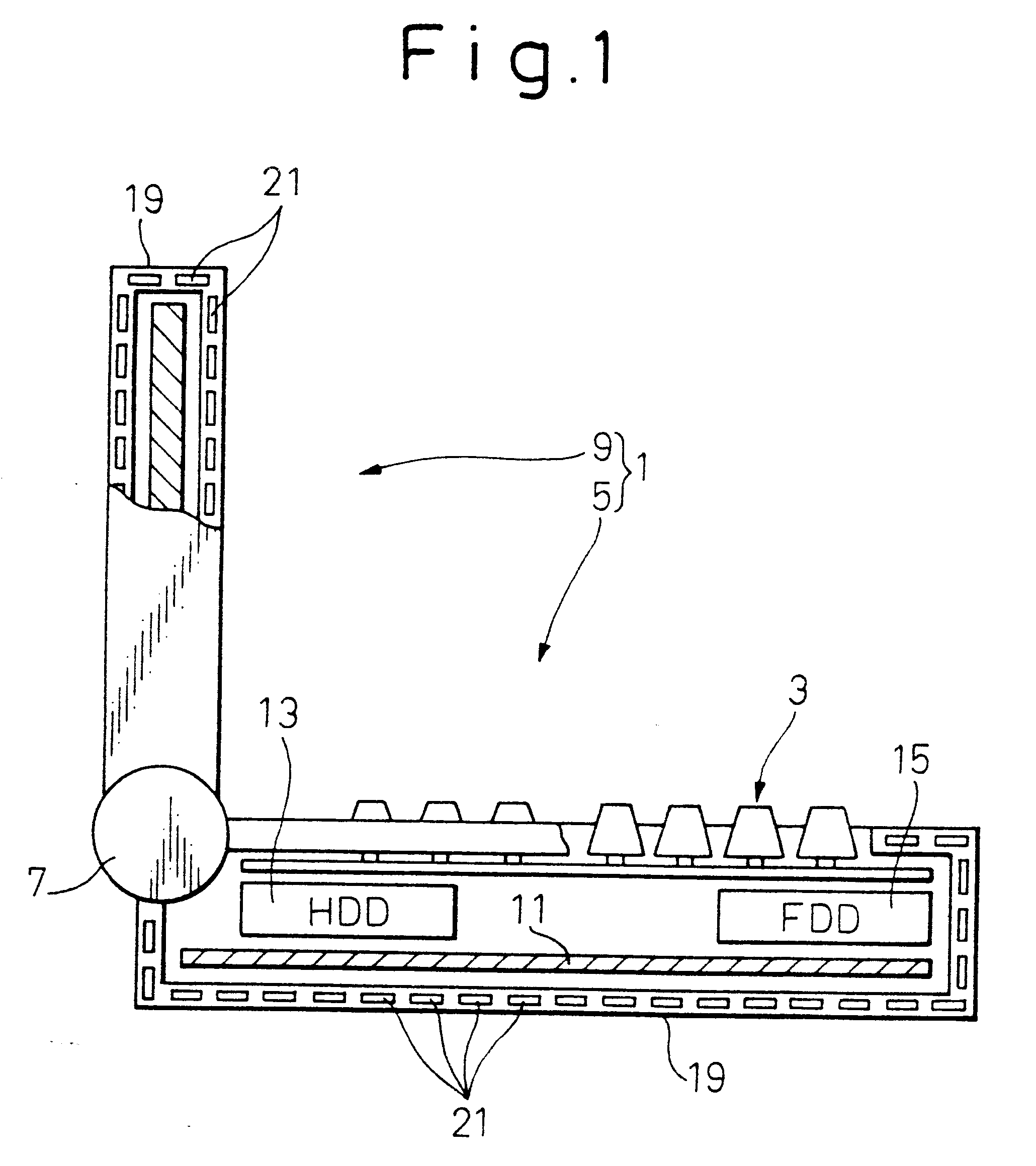
Reference is made to FIG. 1 showing the present invention. The electronic device 1 (for example, a notebook type personal computer) shown in the drawing includes: a main body 5, onto the upper surface of which the key board 3 is mounted; and a liquid crystal display (LCD) 9 pivotally connected to the main body 5 via the hinge portion 7 arranged on the back side (on the left in the drawing) of the main body 5.

The main board 11 is arranged in the inner bottom portion of the main body 5, and the hard disk drive (HDD) 13 and the floppy disk drive (FDD) 15 are incorporated onto the side of the main body 5.

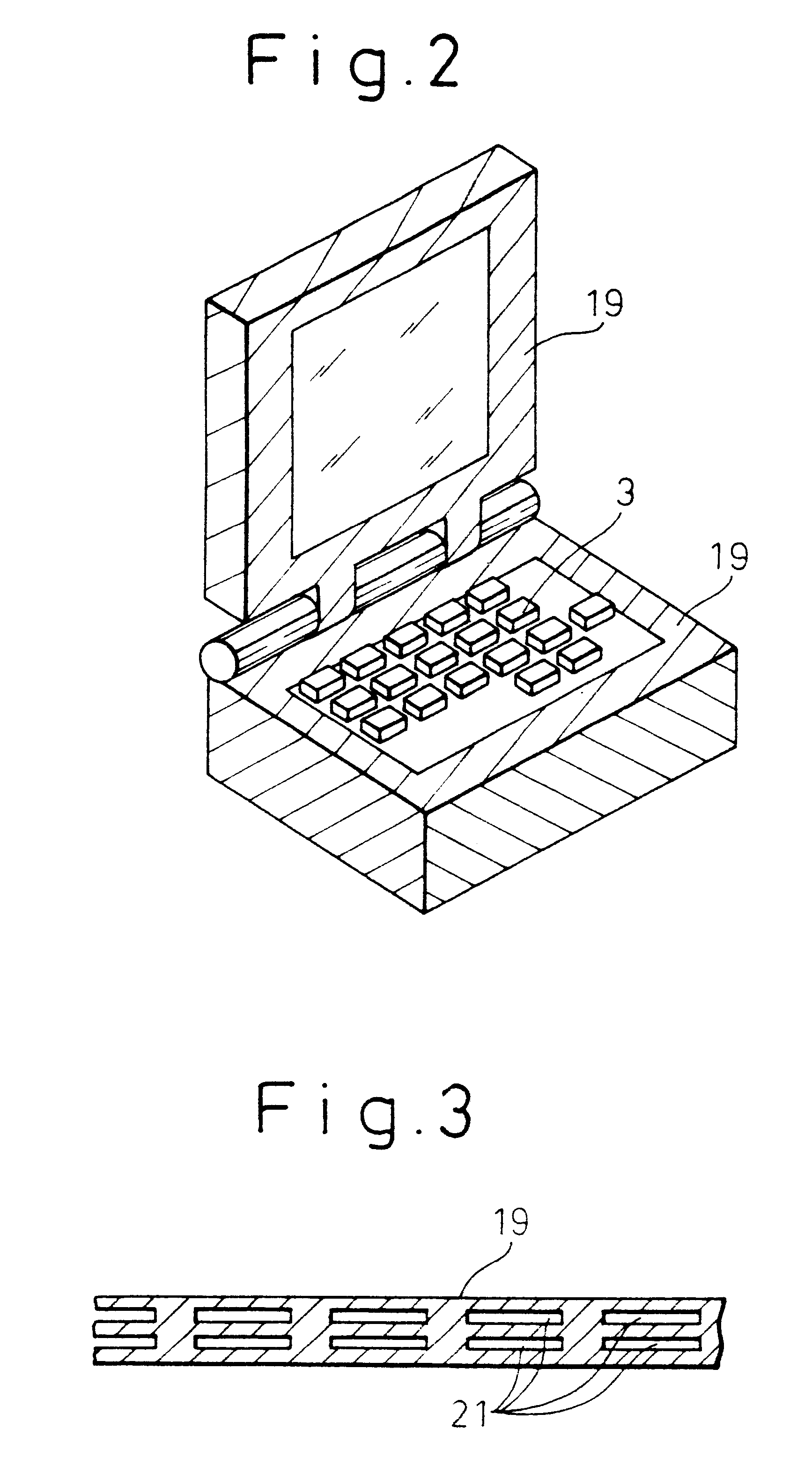
As shown by the hatched lines in FIG. 2, the liquid crystal display 9 (except for the display surface) and the main body 5 (except for the keyboard 3) are covered with the outside panel 19 made of a predetermined resin member. The predetermined resin member is preferably made of material with high heat conduction.

In the.outside panel 19, there are provided a plurality of plate-shaped in...

second embodiment

Reference is made to FIG. 4 showing the second embodiment. The outside panel 29, which covers the liquid crystal display 9 (except for the display surface) and the main body 5 (except for the key board 3), is made of the same material as that of the outside panel 19 of the first embodiment described above, however, the structure is different. That is, the bottom portion of the main body of the outside panel 21 has a plurality of ducts 31 which are partitioned by the partition walls and arranged in parallel to each other.

At the rear of the main body located on the downstream side of the ducts, there is provided a suction type exhaust unit 33. For example, there is provided a fan. In the front of the main body located on the upstream side of the ducts, there is provided an air intake 35.

In the outside panel 29 located in the front of the main body, there are provided a plurality of ducts 31 which are extended in the upward and the downward direction and arranged in parallel to each ot...

third embodiment

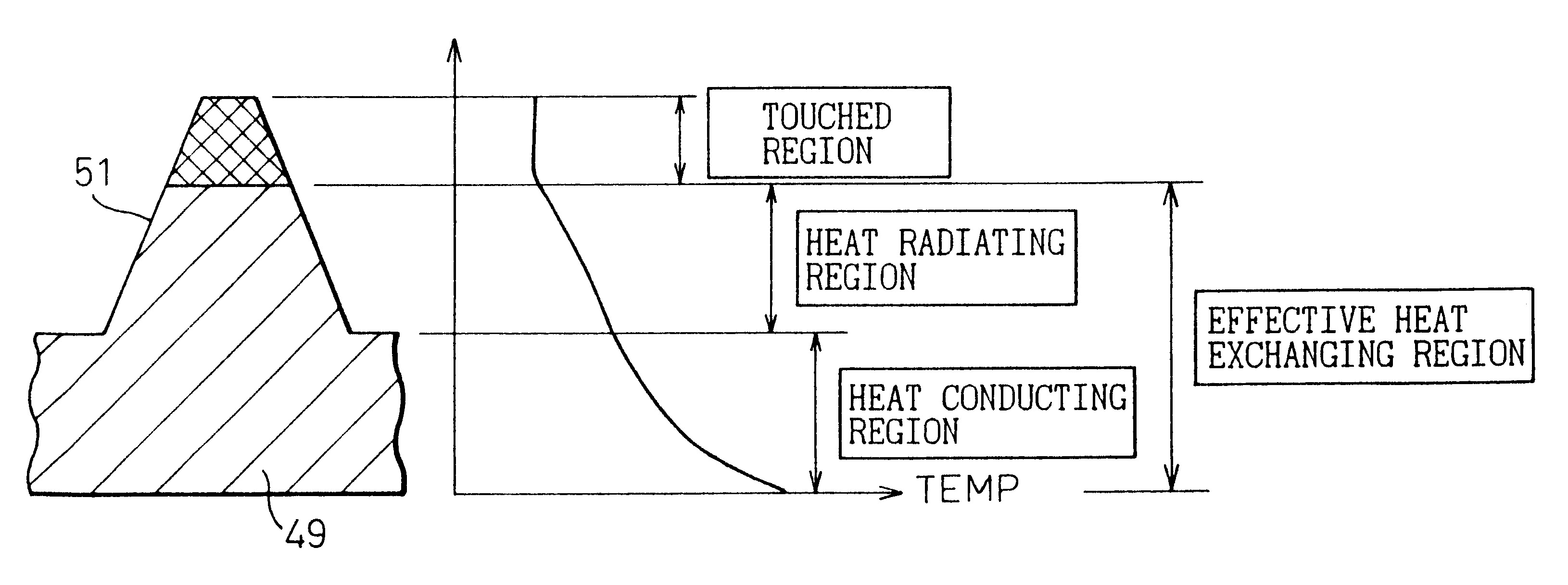
Reference is made to FIG. 6 showing the third embodiment. The outside panel 49, which covers the liquid crystal display 9 (except for the display surface) and the main body 5 (except for the key board 3), is made of the same material as that of the outside panels of the first and the second embodiment described above, however, the structure is different. That is, these outside panels 49 are made of material having a high heat conductivity, and the outer surfaces are provided with a plurality of circular truncated cone protrusions 51 which are regularly arranged.

A forward end portion of the protrusion 51, the length of which is approximately 0.5 mm, is referred to as a touched region with which an operator's hand or a portion of the operator's body actually comes into contact. Therefore, this touched region is subjected to heat insulation treatment. Specific examples of heat insulation treatment are: treatment of coating the touched region with appropriate heat insulation material su...


PUM


Abstract

To prevent an operator from being hurt by a hot outside panel of an electronic device when he touches the outside panel with his hand or a portion of his body, the outside panel is improved and an electronic device safe for the operator is provided. There are provided spaces for heat insulation in an outside panel and, by the action of the spaces, the apparent temperature of the outside panel is decreased. Also, ducts are provided in the outside panel, and the temperature of the outside panel itself is decreased by the action of the ducts. Further, a large number of protrusions are provided on the surface of the outside panel, and a heat insulating section is formed at the forward end of each protrusion, so that the apparent temperature is decreased.

Description

1. Field of the InventionThe present invention-relates to a structure of an outside panel of an electronic device.2. Description of the Related ArtIn the field of electronic devices, especially in the field of portable type electronic information devices (for example, notebook type personal computers), the sizes of the electronic devices have been reduced, the functions have been highly enhanced, and the processing speeds have been greatly increased. Accordingly, a large number of parts, which generate large quantities of heat, are mounted in the electronic devices and the temperatures in the electronic devices are generally very high.In order to effectively emit the heat generated in the devices to the outside, various investigations and a large number of suggestions have been made.For example, Japanese Unexamined Patent Publication No. 63-153924 discloses a structure in which protrusions and recesses are formed on the overall surface of a casing, so that heat can be emitted from t...

Claims


Application Information

Patent Timeline
IPC IPC(8): G06F1/20H05K7/20
CPCG06F1/203
Inventor KATSUI, TADASHIYAMAMOTO, HARUHIKO
Owner FUJITSU LTD
Why Eureka
Try Eureka