Variable capacitor and a variable inductor

a variable capacitor and capacitor technology, applied in variable capacitors, capacitors with electrode area variation, semiconductor/solid-state device details, etc., can solve the problems of inability to achieve reversible impedance change in this circuit, unsuitable for compact rf circuit modules, and inability to achieve multiband or multi-mode impedance matching

Inactive Publication Date: 2003-04-29
NEC CORP
View PDF5 Cites 57 Cited by
  • Summary
  • Abstract
  • Description
  • Claims
  • Application Information

AI Technical Summary

Problems solved by technology

For this reason, there is an increase in the mounting surface area of the matching circuit, making this approach unsuitable for use in compact RF circuit modules.
For this reason, the change in the impedance of the matching circuit is irreversible, making it impossible to use this approach to achieve impedance matching in multiband or multimode applications.
Therefore, it is impossible to obtain reversible impedance change in this circuit.
In technology for providing separate circuitry for each frequency band or each operating mode, although use is possible in a multiband or multimode radio communications apparatus, there is an increase in the number of components used in the RF circuit module, thereby causing the problem of difficulty in achieving a compact, low-cost RF circuit module.
Stated differently, in the conventional art, it is not possible to find and use a reactance element that not only is amenable to reversible impedance change, but also that is compact.

Method used


Image

  • Variable capacitor and a variable inductor
  • Variable capacitor and a variable inductor
  • Variable capacitor and a variable inductor

Examples


Embodiment Construction

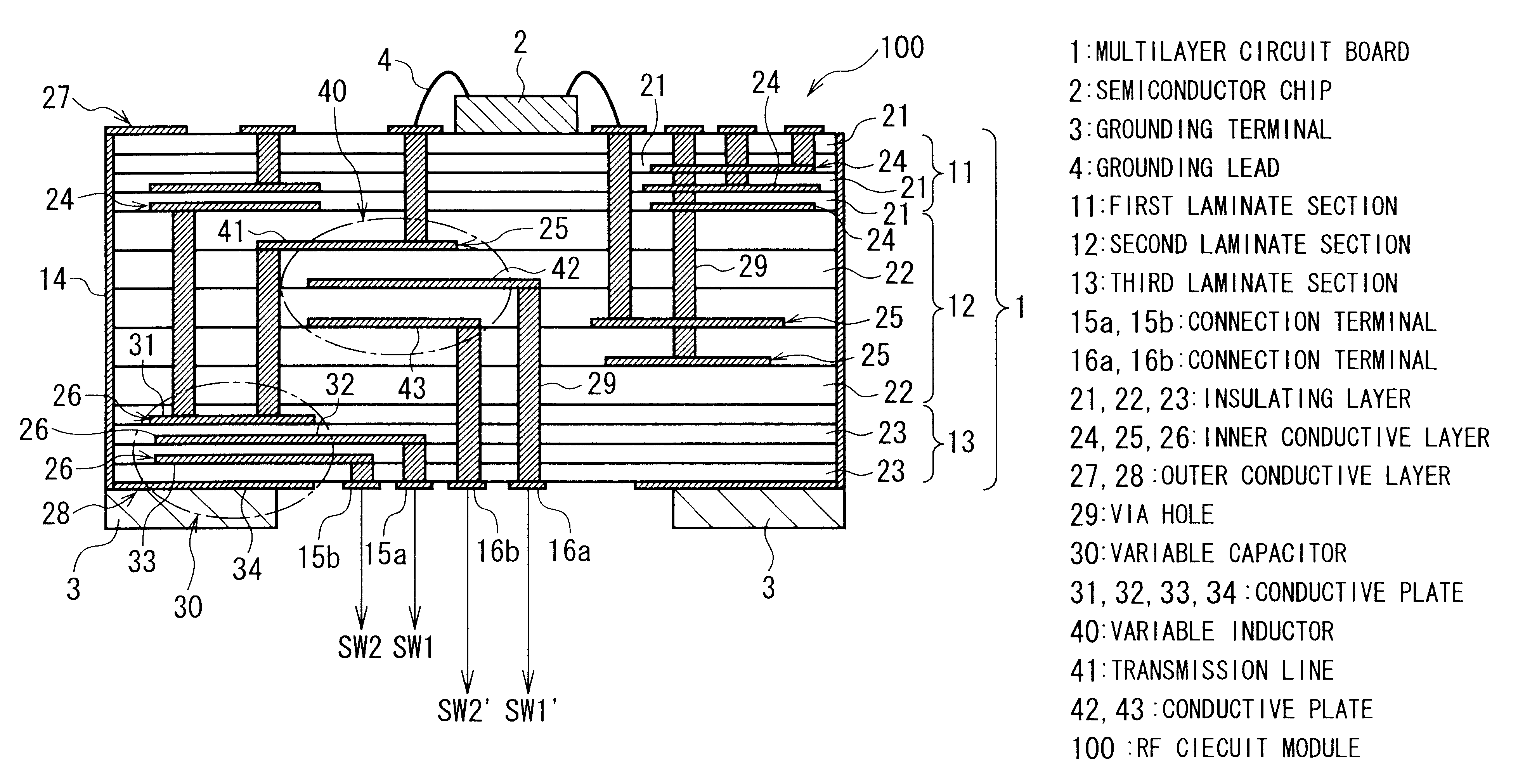
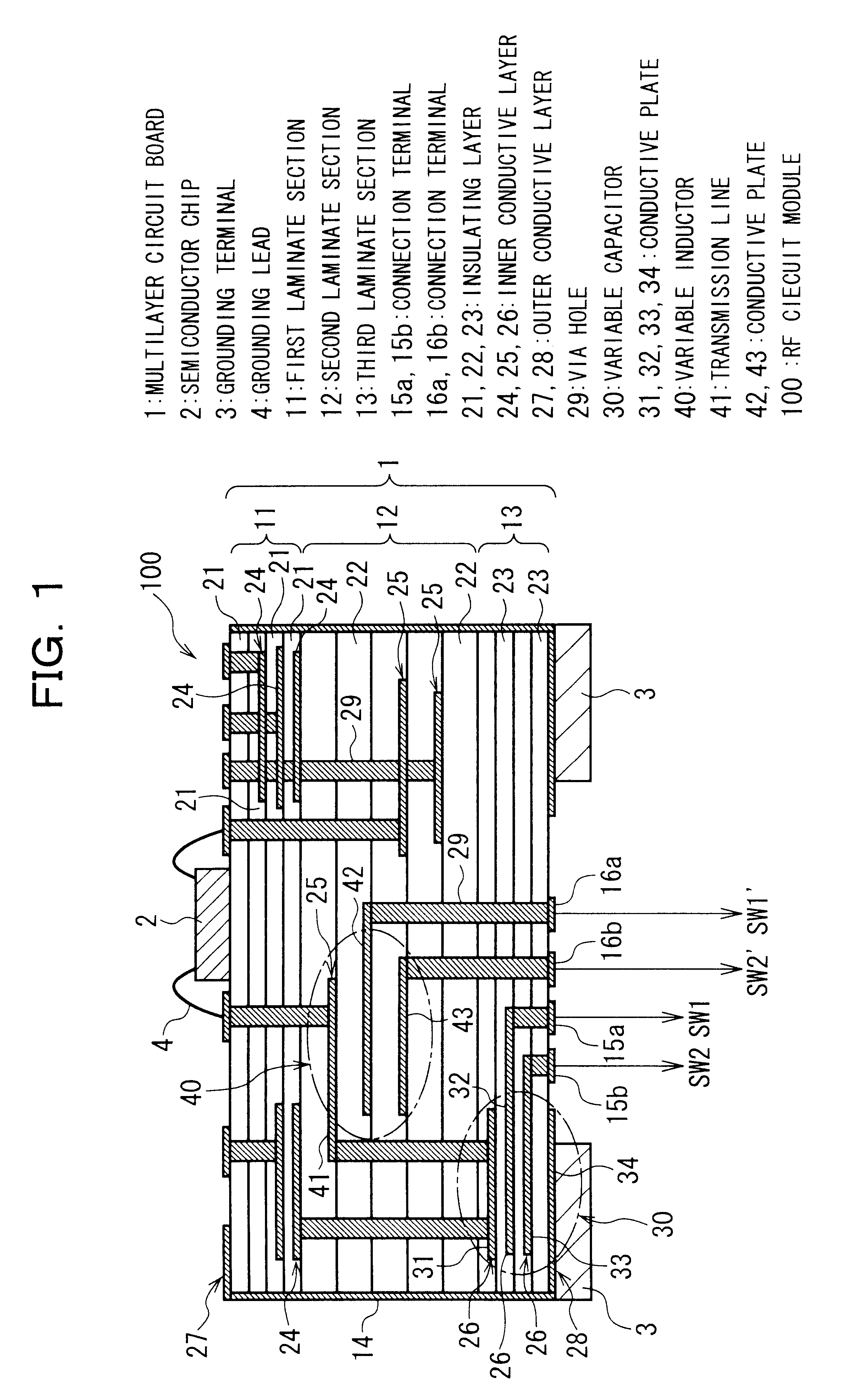
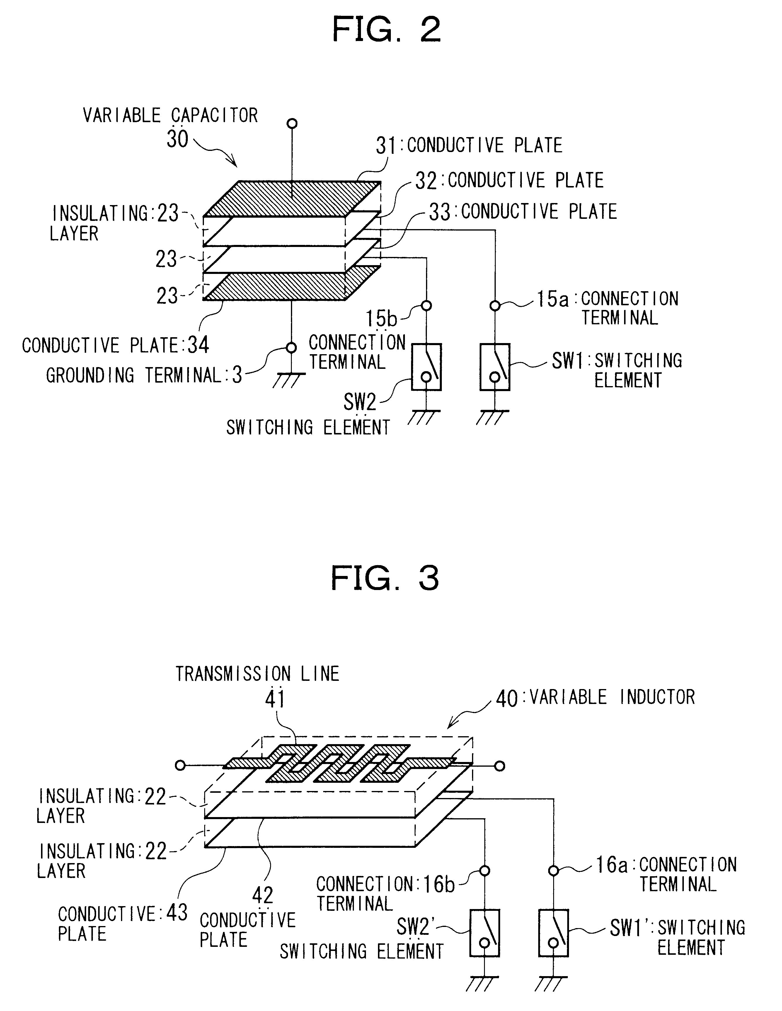
FIG. 14 shows an application example, in which field-effect transistors (FETs) are used as the switch elements SW1 and SW2 connected to the variable capacitor 30 of the first embodiment.

As shown in FIG. 14, in this example the drain of the FET 301 is electrically connected to the conductive plate 32, and the source thereof is grounded. The drain of the FET 302 is electrically connected to the conductive plate 33, and the source thereof is grounded. The control voltages V1 and V2 are supplied to the gates of the FETs 301 and 302.

When the control voltages V1 and V2 are made higher than the threshold voltages of the FETs 301 and 302, the FETs 301 and 302 go into the conducting condition, and the conductive plates 32 and 33 are grounded. If the control voltages V1 and V2 are made lower than the threshold voltages of the FETs 301 and 302, however, the FETs 301 and 302 go into the non-conducting condition, so that the conductive plates 32 and 33 are placed in the electrically floating con...


PUM


Abstract

A variable capacitor is formed by a multilayer circuit board having a plurality of dielectric layers; a first conductive plate, provided within the multilayer circuit board, for serving as one electrode of the variable capacitor; a second conductive plate, provided within the multilayer circuit board, for serving as the other electrode of the variable capacitor; a plurality of third conductive plates provided between the first conductive plate and the second conductive plate; and a plurality of switching means provided for grounding the third conductive plates selectively.

Description

1. Field of the InventionThe present invention relates to a variable capacitor, a variable inductor, and a radio frequency circuit module, and additionally relates to a variable capacitor and a variable inductor suitable for use as passive elements in a radio frequency circuit module, and to radio frequency circuit module having this variable capacitor and variable inductor.2. Related ArtRadio frequency circuits used in radio communications devices such as portable telephones are formed by a large number of components, such as semiconductor transistors, IC chips, and passive circuit, elements such as resistors, capacitors, and inductors. In order to achieve compactness in such apparatuses, modularization techniques, which integrate those components amenable to such integration on one substrate or within one package, is widely used. For example, in an RF amplifier module used in a portable telephone, a transistor which amplifies a high-frequency (radio frequency, RF) signal, an input...

Claims


Application Information

Patent Timeline
Patent Type & Authority Patents(United States)
IPC IPC(8): H01F17/00H01F21/12H03F3/189H03H7/38H03H7/40H03F3/19H05K1/16H05K1/00H01F21/00H01F27/00H01G4/33H01G4/40H01G7/00H01L23/498H01L23/64H01P1/15H03F1/08H03F3/60
CPCH01F17/0006H01L23/49822H01L23/642H03F1/56H03F3/19H03H7/38H03H7/40H05K1/162H01F21/12H01L24/48H01L2224/48091H01L2224/48227H01L2924/09701H01L2924/19041H01L2924/30107H01L2924/3011H01L2924/3025H05K1/0298H05K1/165H05K2201/09672H05K2201/10053H05K2201/10196H01L2924/00014H01L2224/05599H01L2224/45099H01L2224/85399H01L2924/12042
Inventor KUNIHIRO, KAZUAKI
Owner NEC CORP
Why Eureka
Try Eureka