
LD module

a technology of laser diodes and modules, applied in the field of laser diodes, can solve the problems of ld wide beam dispersion sometimes causing difficulties, ld light escapes from the fiber, and all ld light is los

Inactive Publication Date: 2003-05-06
SUMITOMO ELECTRIC IND LTD
View PDF6 Cites 21 Cited by
  • Summary
  • Abstract
  • Description
  • Claims
  • Application Information

AI Technical Summary

Problems solved by technology

The wide beam spread is one of the drawbacks of the current LDs.
The LD wide beam dispersion sometimes induces difficulties.
But almost all of the LD light escapes from the fiber and dissipates in vain due to the wide dispersion (30.degree. to 40.degree.) of the LD light, even if the fiber is brought into direct contact with the LD without gap.
A ball lens is inexpensive but has large aberration.
Aspherical lenses, however, are expensive.
The leak of the light power out of the stripe layer increases the beam diameter.
The narrowing active layer induces insufficient enclosure of the light.
The leak of the light from the active layer enlarges the beam spot size.
The SSC-LD is not an entirely novel device but is not well known for the skilled in art yet.
The use of the lens, however, raises the part cost, the assembling cost and the package cost.
The excess size difference between the fiber and the LD impedes the introduction of the LD beam into the fiber.
If the waveguide of the LD is narrowed, the power of localizing the light power within the waveguide is weakened.
The core-cladding structure is rather an obstacle when the fiber is changed to be a lens at the end.
However, the coupling by the ball-lensed fibers has some drawbacks.
It is difficult to fuse a short, tiny fiber to an end of a narrow single-mode fiber.
It is difficult to make ball lensed fibers with the predetermined size.
The tolerance of the positioning of the end is excessively narrow.
It takes much time to align the fiber and the laser diode.
The device consisting of the ball lensed fiber and the SSC-LD is a sophisticated device but is not suitable for mass-production.
It will be an expensive device.
But complicated finishing raises the cost of manufacturing.
Furthermore, some refracted rays cannot escape from the lens.
It is difficult to solve analytically and exactly Eq.

Method used


Image

  • LD module
  • LD module
  • LD module

Examples


embodiment 2 (

8, 14 and 20 degree aperture angles of LD beams)

embodiment 1

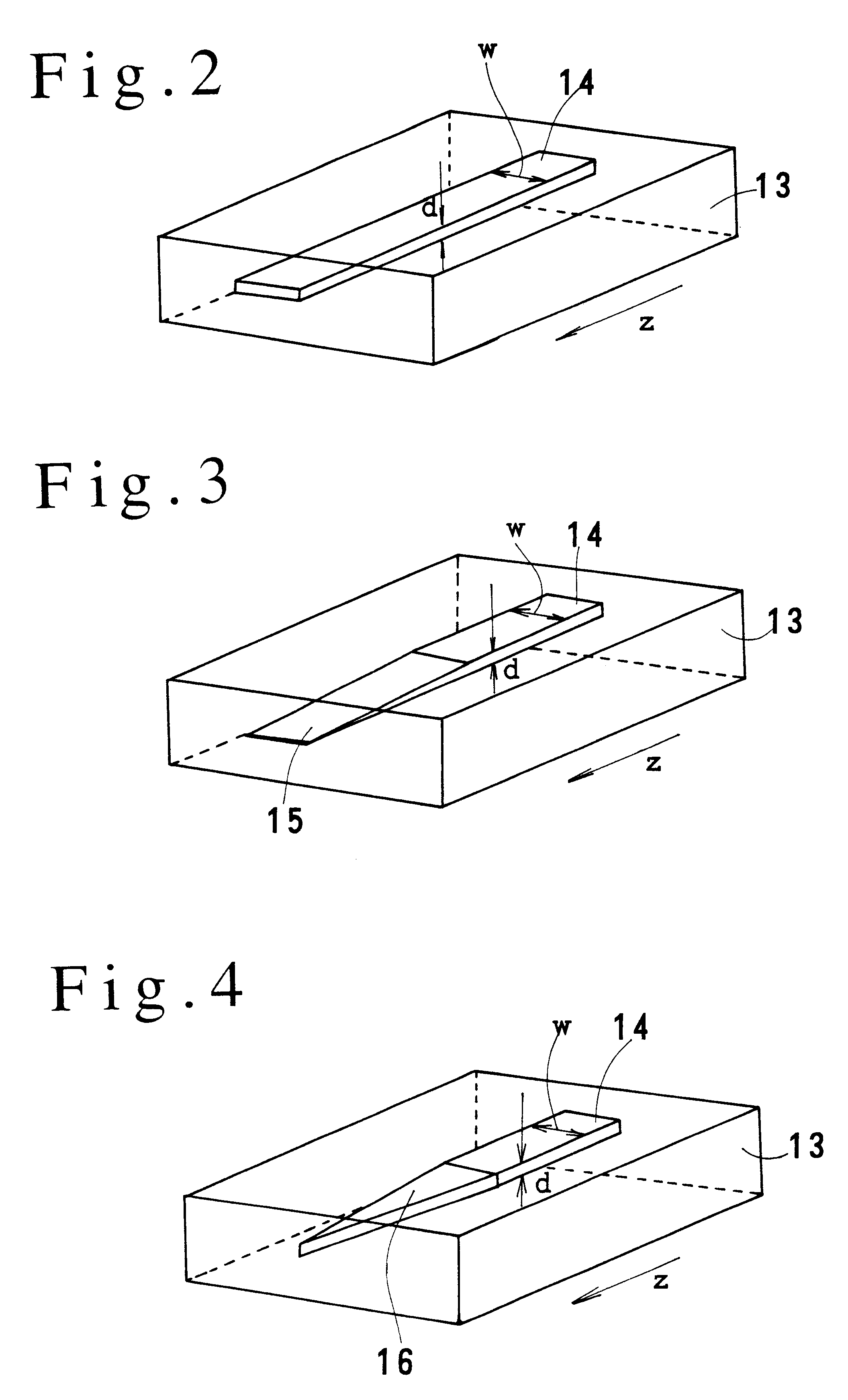
employed a spot-size conversion laser diode (SSC-LD) of a 12 degree aperture angle. Variation of the tapering angle of the active layer enables the SSC-LD to change the aperture angle of the LD beam arbitrarily. The dependence of the coupling efficiency upon the beam aperture is investigated for three SSC-LDs having 8, 14 and 20 degrees of beam aperture angles.

SSC-LD (C) . . . 8 degree of aperture angle

SSC-LD (D) . . . 14 degrees of aperture angle

SSC-LD (E) . . . 20 degrees of aperture angle

These SSC-LD (C),(D) and (E) bring about high coupling efficiency between 20% and 24%.

For comparison examples, similar LD modules having the conventional LDs (35 degrees to 45 degrees of aperture angles) are made. The comparison examples show low coupling efficiency between 10% and 14%.

The present invention can accomplish coupling efficiency 1.5 to 2 times as high as the conventional LD modules. The present invention can give stronger light power to the fiber than the conventional optical transmi...

embodiment 3 (reduction of lens and lens holder ; fig.8 , fig.9)

EMBODIMENT 3 (Reduction of lens and lens holder; FIG. 8, FIG. 9)

The Inventors are aware of the possibility of giving a conspicuous feature to the LD module by employing the spot-size conversion laser diode (SSC-LD). The SSC-LD enables the LD module to be small sized by reducing the lens and the lens holder under the condition of maintaining the same coupling efficiency.

FIG. 8(A) tells us that the ordinary LD uses a wide region of a lens due to the large aperture angle. FIG. 8(B) teaches us that the SSC-LD uses only a central part of a lens due to the narrow aperture angle. The SSC-LD enables the module to employ a smaller diameter lens having the same curvature radius as the conventional LD. A smaller diameter lens than the conventional lens can be sustained by a smaller lens holder than the conventional lens holder. The small beam aperture of the SSC-LD reduces the whole size of the LD module.

FIG. 9(A) and FIG. 9(B) are made by adding lens holders to FIG. 8(A) and FIG. 8(B). FIG. 9...


PUM


Abstract

An LD module having a spot-size conversion LD for emitting a beam of a small aperture angle, an optical fiber or a waveguide and a lens for converging the LD beam to the fiber or the waveguide.

Description

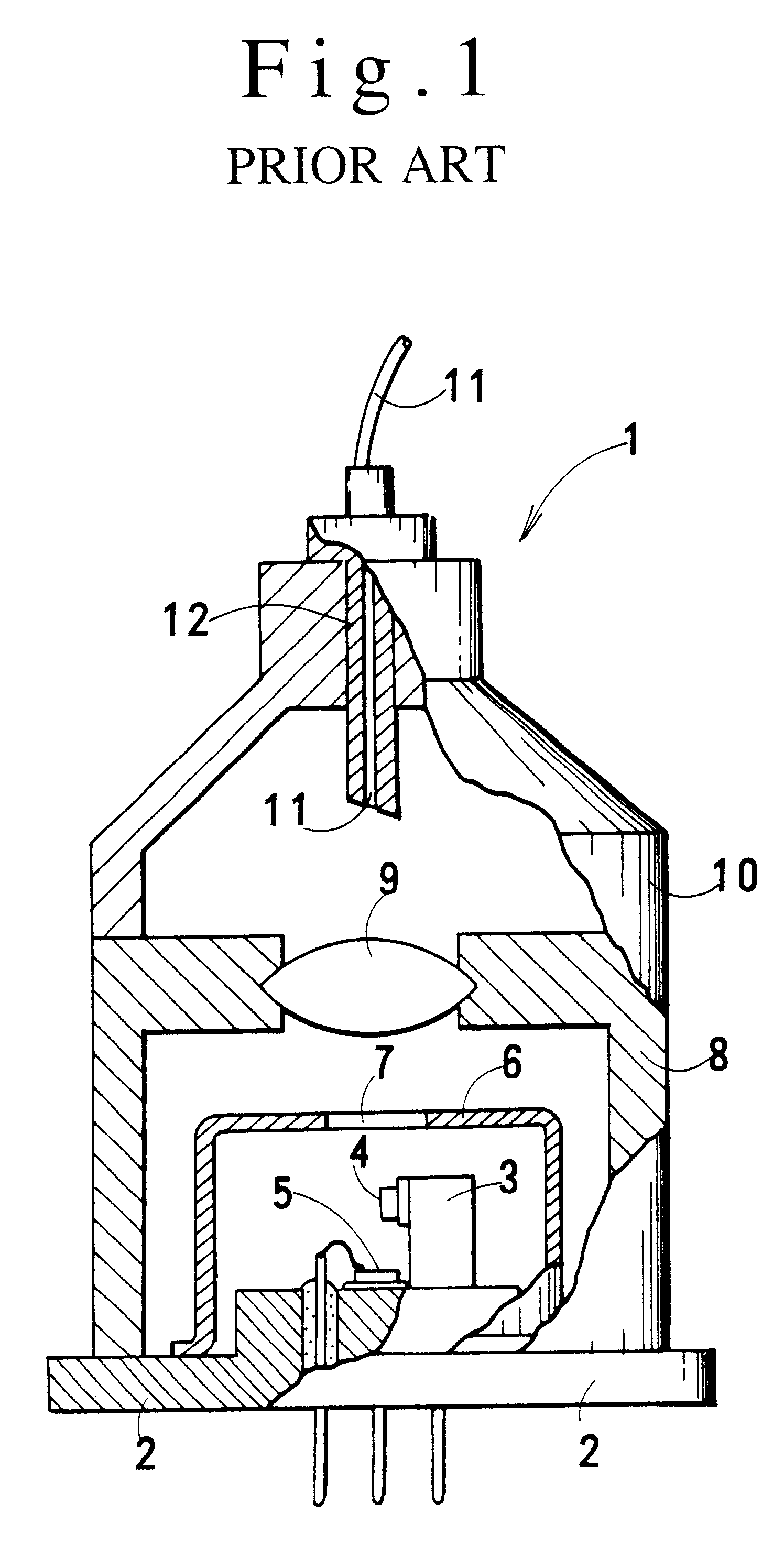
1. Field of the InventionThis invention relates to an LD (laser diode) module, in particular, a low-cost, small-sized and high-performance LD module which is utilized in optical communication systems.This application claims the priority of Japanese Patent Application No.2000-147867 filed on May 19, 2000 which is incorporated herein by reference.2. Description of Related ArtFIG. 1 shows a prior art LD module 1 which is sealed in a vertical metal case. This is one of the most prevalent LD modules at present. The transmitting (LD) module 1 has a metallic package. A circular metal stem 2 has a pole 3 erected near the center. An LD (laser diode) 4 is bonded on a side of the pole 3. A top incidence type PD 5 is mounted with a light receiving surface upward at the center of the stem 2. A cylindrical metal cap 6 is welded on the stem 2 for covering the LD 4 and the PD 5. The cap 6 has a top opening 7 for guiding the LD light outward.A metallic cylindrical lens holder 8 is welded outside of ...

Claims


Application Information

Patent Timeline
Patent Type & Authority Patents(United States)
IPC IPC(8): G02B6/42H01S5/022H01S5/00G02B6/12H01S5/026H01S5/10
CPCG02B6/4206G02B6/4292H01S5/1014H01S5/02212H01S5/02284G02B2006/12195H01S5/02251
Inventor KUHARA, YOSHIKINAKANISHI, HIROMIYOSHIMURA, MANABU
Owner SUMITOMO ELECTRIC IND LTD
Learn More