Internal combustion engine control system
a control system and combustion engine technology, applied in the direction of machines/engines, non-mechanical valves, output power, etc., can solve the problems of increased pumping loss, reduced combustion efficiency, and increased loss, so as to reduce fuel consumption, reduce pumping loss, and achieve satisfactory combustion
- Summary
- Abstract
- Description
- Claims
- Application Information
AI Technical Summary
Benefits of technology
Problems solved by technology
Method used
Image
Examples
first embodiment
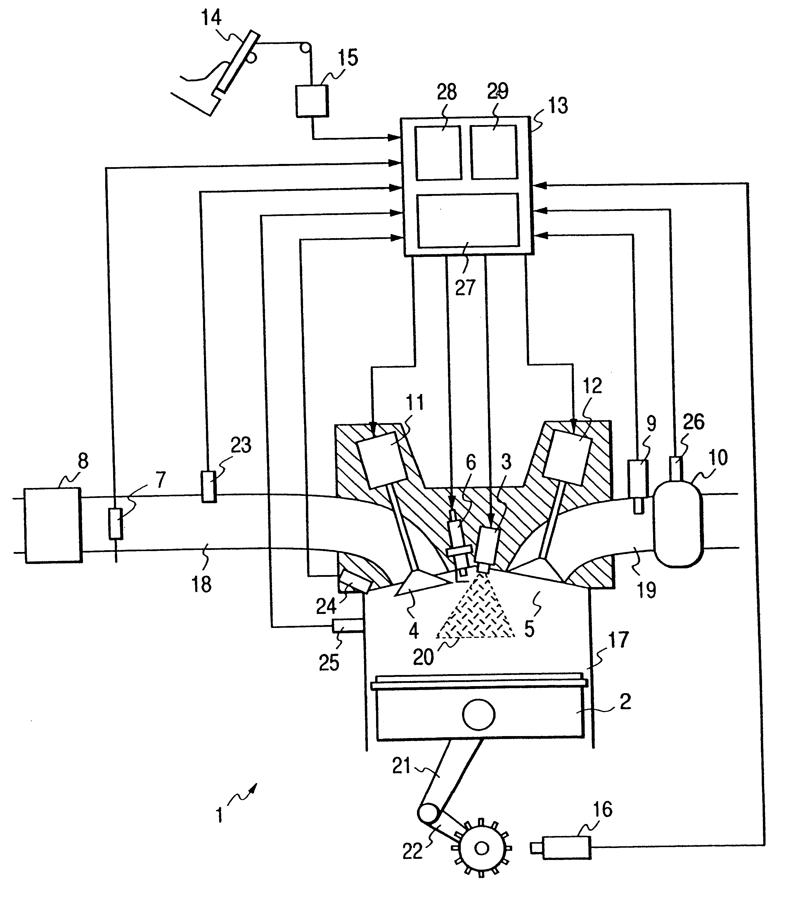
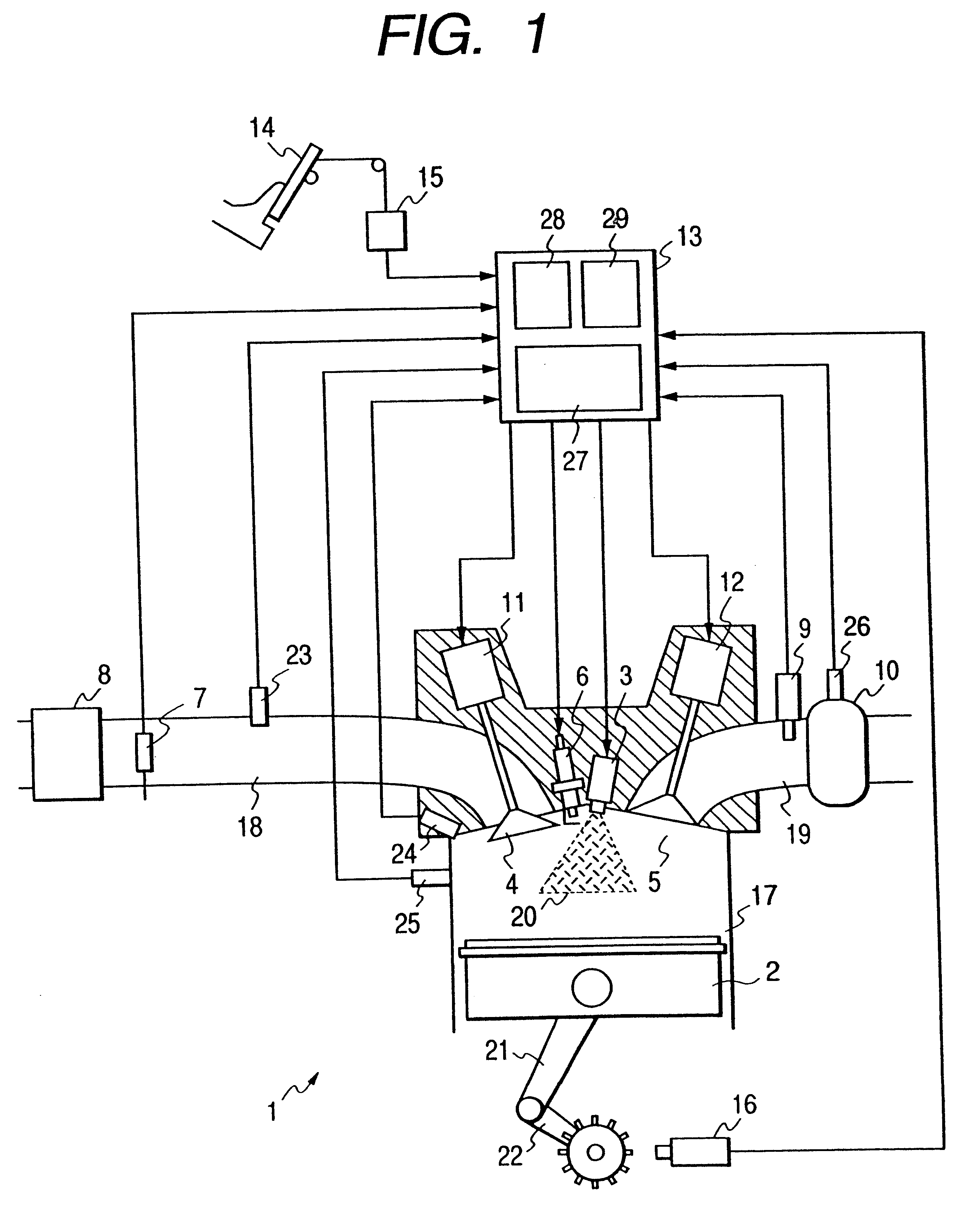
FIG. 1 is a view showing the configuration of the present invention and illustrating one of the cylinders of an engine in a sectional view. Referring to FIG. 1, an engine 1 is provided with a piston 2, a fuel injector 3, a intake valve 4, an exhaust valve 5, an ignition plug 6, a combustion chamber pressure sensor 24 for sensing pressure in a combustion chamber, and a knocking sensor 25. A intake pipe 18 is provided with an air flow sensor 7, an air cleaner 8 and a intake pipe pressure sensor 23 for sensing pressure in the intake pipe 18. An exhaust pipe 19 is provided with an air / fuel ratio sensor 9, a catalytic unit 10, and a catalyst temperature sensor 26 for sensing catalyst temperature, i.e., the temperature of the catalytic unit 10. Signals provided by the air flow sensor 7, the intake pipe pressure sensor 23, the combustion chamber pressure sensor 24, the knocking sensor 25, the air / fuel ratio sensor 9, the catalyst temperature sensor 26 and a crank angle sensor 16 are given ...
second embodiment
FIGS. 12 and 13 show the present invention. FIG. 12 is a graph showing the variations of valve lift, fuel injection quantity and air / fuel ratio with the stepping-on measurement of an accelerator pedal. A stepping-on measurement of the accelerator pedal represents an engine output demanded by the driver. It is considered that a high engine output is demanded when stepping-on measurement of the accelerator pedal is large, and it is considered that not a very high engine output is demanded when stepping-on measurement of the accelerator pedal is small. An engine like that of the present invention not provided with any throttle valve in the intake system needs to control intake air quantity to be sucked into the combustion chamber of the engine by the intake valve. Since the quantity of air flowing through the intake valve is roughly proportional to the area of an opening formed by lifting the intake valve, air quantity can be estimated from the lift of the intake valve. This method is ...
third embodiment
FIG. 14 is a graph of assistance in explaining the present invention. Usually, engine output is increased by increasing intake air quantity to provide driving power for driving an engine accessory, such as an air conditioning system while an engine is operating under a very light load, i.e., while the engine is idling. In a conventional engine provided with a throttle valve, intake air quantity is regulated by opening and closing a bypass passage bypassing the throttle valve by a valve disposed in the bypass passage for the fine adjustment of air quantity without opening the throttle valve, which, however, increases the number of parts and increases the costs. In the engine 1 illustrated in FIG. 1, the variable valve timing mechanism of the present invention keeps the open period and the valve lift of the intake valve constant and regulates intake valve opening timing and suction valve closing timing minutely to regulate the engine speed and the driving force of the engine. When the...
PUM
 Abstract
Description
Claims
Application Information
 - R&D
- Intellectual Property
- Life Sciences
- Materials
- Tech Scout
- Unparalleled Data Quality
- Higher Quality Content
- 60% Fewer Hallucinations
Browse by: Latest US Patents, China's latest patents, Technical Efficacy Thesaurus, Application Domain, Technology Topic, Popular Technical Reports.
© 2025 PatSnap. All rights reserved.Legal|Privacy policy|Modern Slavery Act Transparency Statement|Sitemap|About US| Contact US: help@patsnap.com


