
Self-contained steam trap monitor

a self-contained, steam trap technology, applied in the direction of liquid/fluent solid measurement, instruments, nuclear elements, etc., can solve the problems of large number of steam traps, difficult access to steam traps, and difficulty in locating the steam traps themselves

Inactive Publication Date: 2003-05-27
TYCO VALVES & CONTROL INC
View PDF11 Cites 30 Cited by
  • Summary
  • Abstract
  • Description
  • Claims
  • Application Information

AI Technical Summary

Benefits of technology

The monitor of the present invention is self-contained, can be easily moved from one monitored component to another, can be reprogrammed for use with a different component, is self-powered, and is independent of a connecting network with a central processing unit. The self-contained, on-site position of the monitor provides an immediate identification of the component being monitored with an immediate and continuous indication of the component's operating status. Low power requirements, an efficient program and reprogrammable microprocessing circuitry within the monitor provide long life, portability, and versatility to the monitor.
The automated, self-contained features of the monitor of the present invention are independent of operator skill, operator presence, or operator intervention. The lack of reliance on operator interpretation and presence increases the speed, accuracy, and efficiency of the monitoring system of the present invention. Continuous monitoring of the control device produces immediate recognition of abnormal operation so that timely action may be taken to correct or prevent undesired operating conditions.
An important object of the present invention is to provide a self-contained monitor that can be physically secured to a steam trap to provide continuous monitoring and status reporting of the condition of the steam trap. It is also an object of the invention to provide a readily discernible indication of such condition, such as by the illumination of different colored lights included as a part of the monitor whereby the condition of the monitor can be readily apparent to an inspector without the need for coming into physical contact with the steam trap or tracing the location of the steam trap from information obtained from a central monitor.

Problems solved by technology

Failure of the steam trap in a steam system can produce serious system damage and loss.
In larger systems, the number of steam traps can be large, and the steam traps themselves may be difficult to access as well as to locate.
Manual monitoring of steam traps can thus be difficult simply from the standpoint of locating a specific steam trap and then obtaining access to the steam trap once it has been located.
The monitoring of this prior art system is not designed to be continuous for a particular steam trap and requires the physical presence of an operator at each steam trap during the monitoring.
In addition to the reliance on operator presence and skill, the Yumoto et al. technique suffers from the fact that the specific steam trap being monitored, even when operating properly, will not necessarily adhere to a "standard" operating pattern in a particular environment.
The Hill et al. system is not self-contained and does not provide an alarm or signal at the monitored component that identifies the location and condition of the component.
The transducers and processing components required to implement the system are complex and expensive.
As with the Yumoto et al. system, the Hill et al. system is not well-suited for continuous automated monitoring of valve operation.
While the technique compares baseline data with on-line data for system evaluation purposes, individual control components in the system are not continuously monitored, and the condition or status of an individual control component is not automatically signalled by a self-contained monitor associated with the control component.
The Speranza system does not provide continuous monitoring and does not provide automatically generated signals associated with a specific monitored component to show the location of the component and to signal the status or condition of the component.
The concept of "standard" operation as a reference in continuously monitored systems is complicated by the fact that in the operation of a typical system, it is necessary to periodically shut down the system for either maintenance or repair or to modify the system design or operation.
Such changes in system operation, when monitored by a system that employs only on-line operating conditions as the basis for establishing a standard baseline data set, may indicate abnormal operation of a steam trap that is in fact operating properly.

Method used


Image

  • Self-contained steam trap monitor
  • Self-contained steam trap monitor
  • Self-contained steam trap monitor

Examples


Embodiment Construction

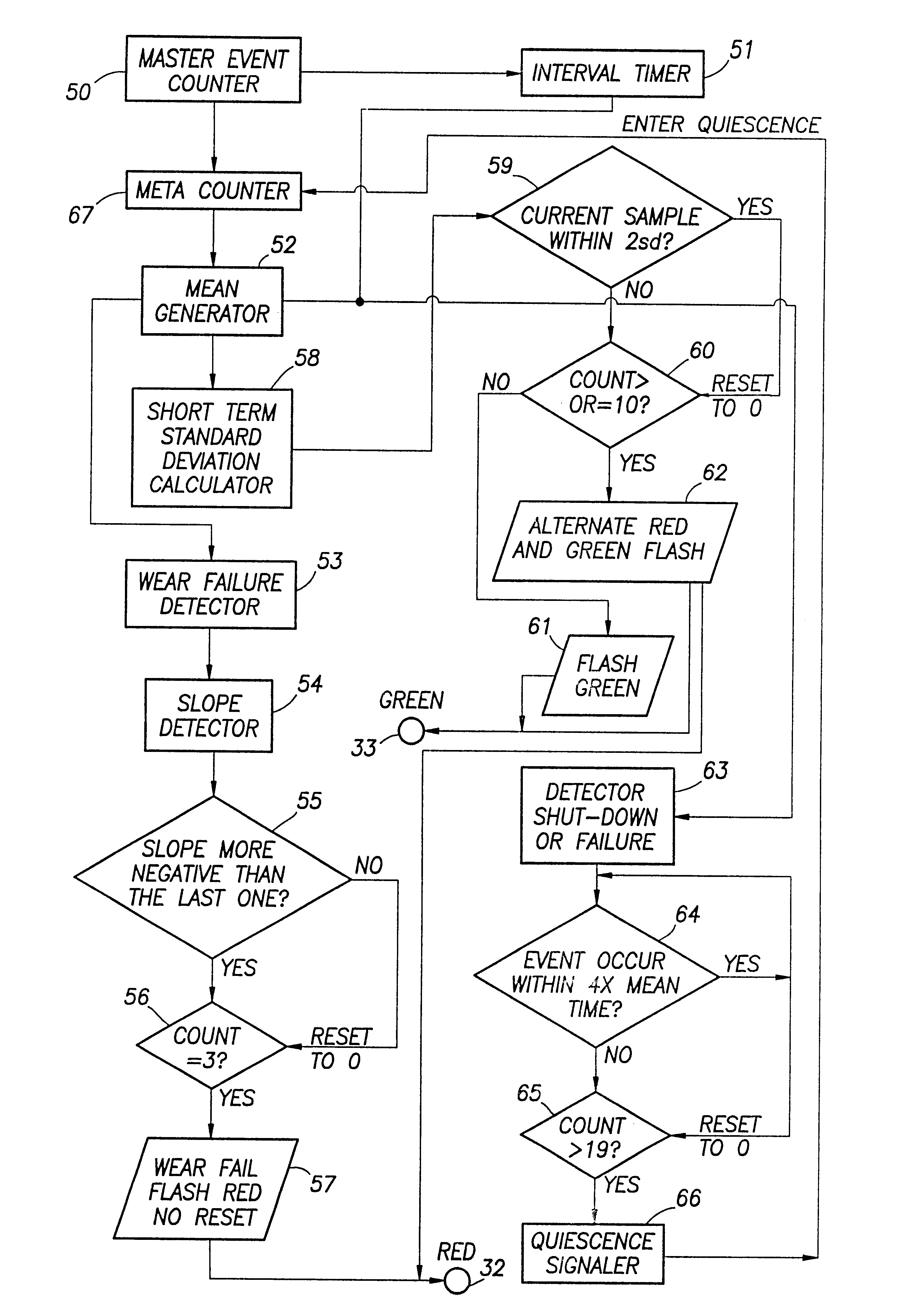
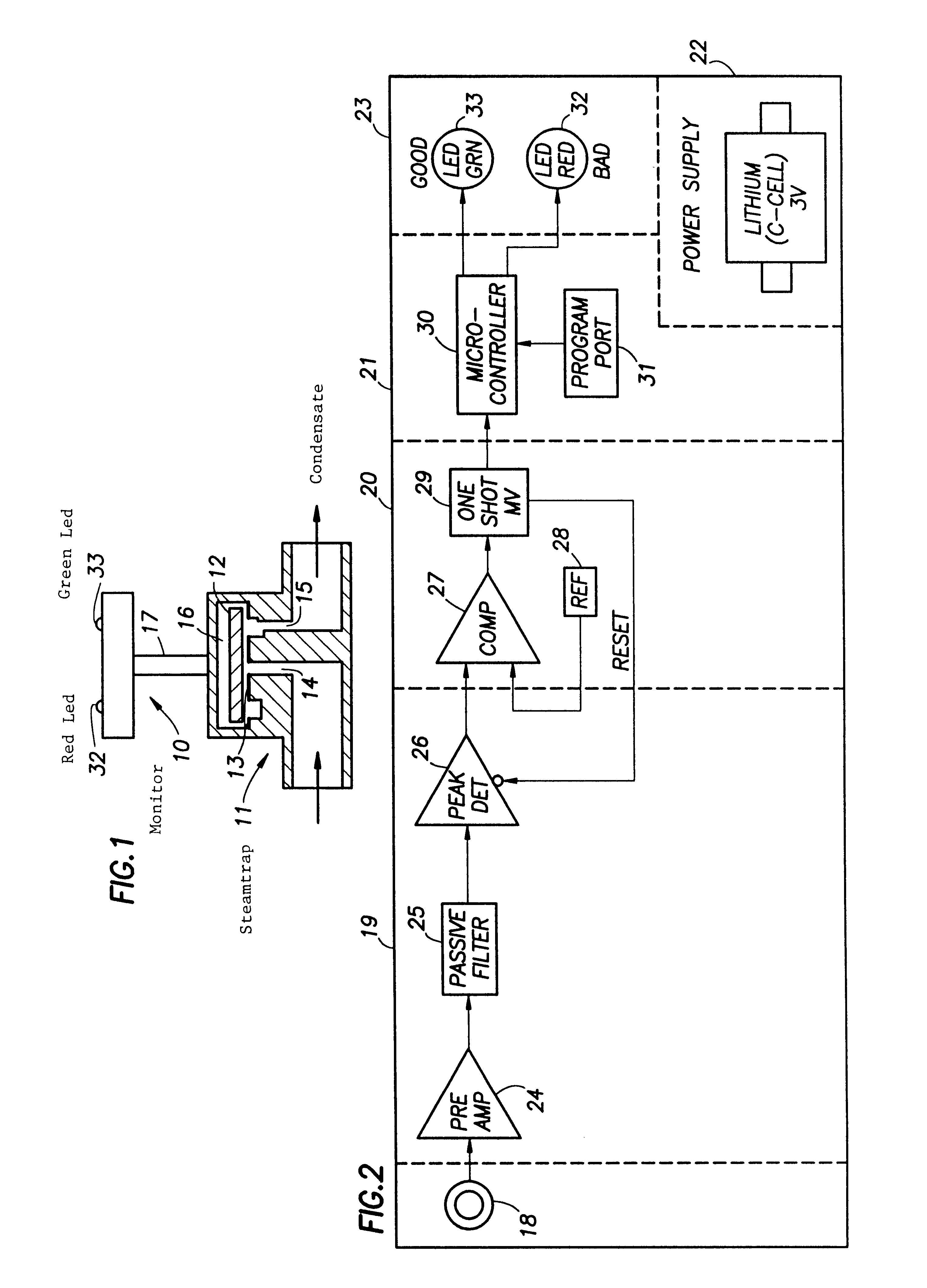
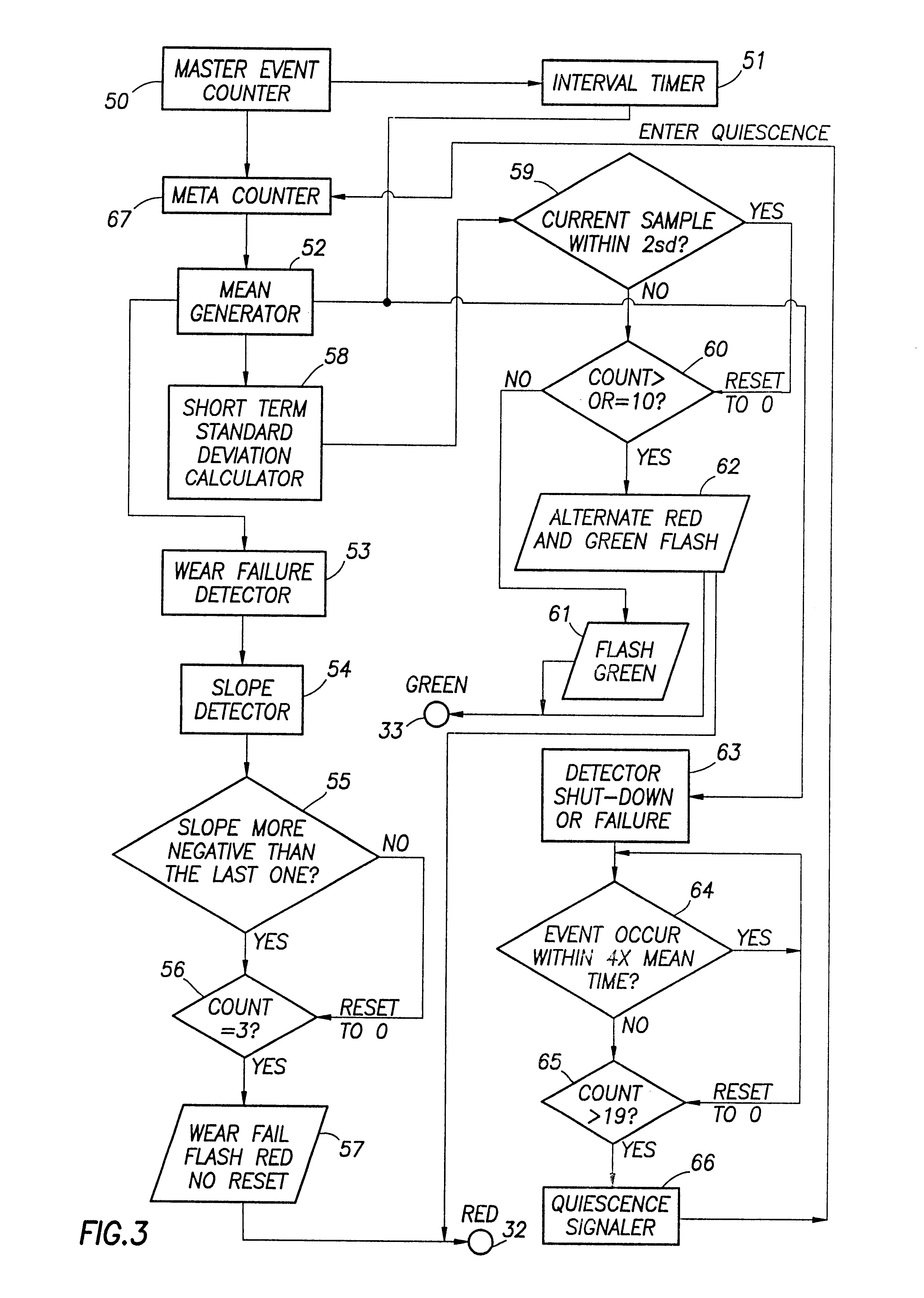
The self-contained monitor of the present invention is indicated generally at 10 in FIG. 1 mounted on the bonnet of a conventional disk-type steam trap indicated generally at 11. The disk trap 11 utilizes the heat energy in hot condensate within the system (not illustrated) in which the steam trap operates and the kinetic energy in steam to open and close a valve disk 12. The disk trap 11 is a phase detector, sensing the difference between liquid and gas or vapor.

During initial start-up, pressure created by cold condensate pushes the valve disk 12 off a seating surface 13, which uncovers an inlet port 14 and discharge outlet port 15, allowing discharge of the condensate from the system. As the condensate reaches the inlet port 14 (a restriction), it experiences a decrease in pressure and an increase in velocity. If the condensate is very close to steam temperature, the lower pressure will cause it to flash into steam. The resulting high velocity flow beneath the disk 12, with its at...


PUM


Abstract

A self-contained system to continuously monitor a mechanism used to process, control or regulate fluid flow or pressure and provide a continuing indication of the status or condition of the monitored mechanism. A specific form of the invention employs a low frequency sonic-to-electrical transducer that monitors opening and closing of a disk-type steam trap. The detected sonic signal is processed and sent to a microprocessor that is programmed to develop a time-based, baseline data set representative of normal operation of the steam trap in the environment in which it operates. The baseline data set is compared with the data from on-line operations of the steam trap. As the environment and the steam trap operation change during normal on-line operations, the baseline data set is updated to change with the changing environment and the changing steam trap operation.

Description

1. Field of the InventionThe present invention relates to the field of monitoring the operations of devices used in fluid systems. More specifically, the present invention applies to the field of monitoring steam trap operation to detect and predict abnormal operation of the steam trap.2. Description of the Prior ArtTypical steam-containing systems require that condensed fluids and some uncondensed gases be discharged from the steam to prevent system malfunction. To this end, a variety of devices have been employed to automatically discharge undesirable gases and condensate from steam-containing systems. These devices, referred to generally as steam traps, can operate in a variety of ways to perform the basic task of venting undesired gases and condensates from the steam system.Failure of the steam trap in a steam system can produce serious system damage and loss. It is customary, therefore, to periodically monitor the operation of the various steam traps in the system to detect mal...

Claims


Application Information

Patent Timeline
IPC IPC(8): F16T1/00F16T1/48G01M13/00
CPCF16T1/48G01M3/24
Inventor TURNER, JOHN M.NETHERS, JAN L.
Owner TYCO VALVES & CONTROL INC
Learn More