Multiple microchannels chip for biomolecule imaging, and method of use thereof

a biomolecule and microchannel technology, applied in the direction of optical radiation measurement, spectral modifiers, radiation measurement, etc., can solve the problems of vacuum pressure, undesirable artifact generation, and difficult structure integrity of glass samples, and achieve uniform test conditions.

Inactive Publication Date: 2003-07-01
ROYCE TECH
View PDF34 Cites 28 Cited by
  • Summary
  • Abstract
  • Description
  • Claims
  • Application Information

AI Technical Summary

Benefits of technology

An important object of the present invention is therefore to improve upon the above-noted prior art technology, in particular to that disclosed in the Beattie patent, supra, by providing a device which will be able to perform a large number of bio molecule tests simultaneously, as well as producing a uniform test environment for each biomolecule test and eliminate the statistical test to test variations.

Problems solved by technology

Threshold values are such that, below 10 micrometers in channel diameter, increase in vacuum pressure is required to force water through the microchannels, and also structural integrity of the glass sample then becomes problematic.
However, on the other side, by increasing channel diameter beyond 10 microns and reducing the thickness of the glass plate, vacuum pressure is still required but to a lesser extent, while undesirable artifacts are generated in particular increased diffuse halos around the top access mouth of the channels.
These undesirable artifact halos considerably deteriorate both the image quality and the sensitivity of the test.
However, such prior art microscopic detection devices usually require charged coupling devices, and cannot scan the full sample area.
This is because, as in the Beattie patent, since you have vertical micro-channels, the diameter thereof larger than 10 micrometers will produce much larger optical halo artifacts and will bring about much diminished microscopic sensitivity.

Method used


Image

  • Multiple microchannels chip for biomolecule imaging, and method of use thereof
  • Multiple microchannels chip for biomolecule imaging, and method of use thereof
  • Multiple microchannels chip for biomolecule imaging, and method of use thereof

Examples


Embodiment Construction

.

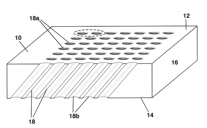
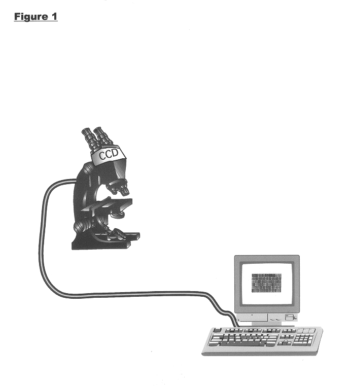
FIGS. 3 and 5 of the drawings show prior art microchannels such as in the Beattie patent, supra. Each such microchannel is a regularly array of the unilength type in perpendicular position to the surface of the plane. It is vertical or upright, inside the glass observation plate. This microchannel is of uniform length and shape, and is vertical. As further shown in FIG. 1, it needs to be scanned through the entire length of the channel for detection, it requires special scanning device, and is therefore expensive. It has average emission excitation, a cross-talk, and a halo circle around the top sample access end mouth constituting an artifact. It has average to low sensitivity. Its maximum operational diameter is 10 micrometers or less. It further needs seals and vacuum pressure to engage the water sample inside the microchannel, due to the microchannel diameter being too small for unassisted engagement.

As is shown in prior art FIG. 3A, there is a top end view of two adjacent chan...


PUM

PropertyMeasurementUnit
diameteraaaaaaaaaa
diameteraaaaaaaaaa
diameteraaaaaaaaaa

Abstract

A panel chip for supporting biological samples for observation with a microscope. The glass panel defines a top flat surface, a bottom bearing surface, and at least a few channels extending generally parallel to each other from top to bottom surfaces. Each of the channels defines a top access mouth for ingress of biological samples, wherein each channel is obliquely inclined so as to make a significant acute angle relative to an axis perpendicular to said top flat surface, in order to facilitate the guidance of maximum light into the channel due to zero loss of reflection and to produce the maximum number of total internal reflection and to guide the maximum light out of the microchannel in such a manner that produces no artifact halo for maximum detection and sensitivity. Each channel has such an inner diameter as to accommodate flow through viscosity of a biological sample containing fluid.

Description

This invention relates to providing a microchannel chip device which will be able to perform a large number of bio molecule tests simultaneously, as well as producing a uniform test environment for each biomolecule test and eliminate the statistical test to test variations.BACKGROUND INVENTIONIt is known in fluid dynamics that, due to the viscosity of the biological sample containing fluid, which is usual water, the dynamic pressure to pass this fluid through and into the multiple channel glass panel increases as the microchannel diameter is reduced and the glass plate thickness increases. Threshold values are such that, below 10 micrometers in channel diameter, increase in vacuum pressure is required to force water through the microchannels, and also structural integrity of the glass sample then becomes problematic. However, on the other side, by increasing channel diameter beyond 10 microns and reducing the thickness of the glass plate, vacuum pressure is still required but to a l...

Claims


Application Information

Patent Timeline
Patent Type & Authority Patents(United States)
IPC IPC(8): B01L3/00G01N21/64G02B21/34G02B21/36G01N21/03B01J19/26C12M1/00C12M1/40C40B30/04C40B40/02C40B50/06C40B60/12G01N33/483G01N33/53G01N37/00
CPCB01L3/5025G01N21/6428G01N21/6452G02B21/34G02B21/361G01N21/0303G01N21/05G01N2021/0325G01N2021/0346Y10S977/704B01L3/00
Inventor RAHBAR-DEHGHAN, FARIBORZ
Owner ROYCE TECH
Why Eureka
Try Eureka