Optical sensing system

a technology of optical sensing and optical sensing tube, which is applied in the field of fiber optic sensors, can solve the problems of marine seismic streamers of such individual sensors being bulky and expensive to fabricate, and the two-tail system has not been considered practical or economical for use in marine seismic streamers, and achieves the effect of improving operational performan

Inactive Publication Date: 2003-07-08
ION GEOPHYSICAL CORP
View PDF9 Cites 100 Cited by
  • Summary
  • Abstract
  • Description
  • Claims
  • Application Information

AI Technical Summary

Benefits of technology

The present embodiments of the invention provide optical sensing systems having enhanced operational performance through the use of features such as, for example, time division multiplexing and wave division multiplexing, optical amplifiers, and optical switches.

Problems solved by technology

Pressure changes about a hydrophone cause deformations, which in turn cause phase modulation of light traveling through the fibers within each discrete hydrophone.
Marine seismic streamers of such individual sensors are bulky and expensive to fabricate.
These two-tail systems have not been considered practical or economical for use in marine seismic streamers.
Such conventional optical sensing systems are also limited in their application by cross talk effects.
In seismic acquisition, cross-talk of acoustic signals between sensors is highly deleterious to processing data.
To achieve this level of crossfeed the reflectivity of the mirrors would have to be so low that there would be inadequate returned optical power to process.

Method used


Image

  • Optical sensing system
  • Optical sensing system
  • Optical sensing system

Examples


Embodiment Construction

Those elements of the present illustrative embodiments having the same numerical label are preferably substantially identical in design and operation.

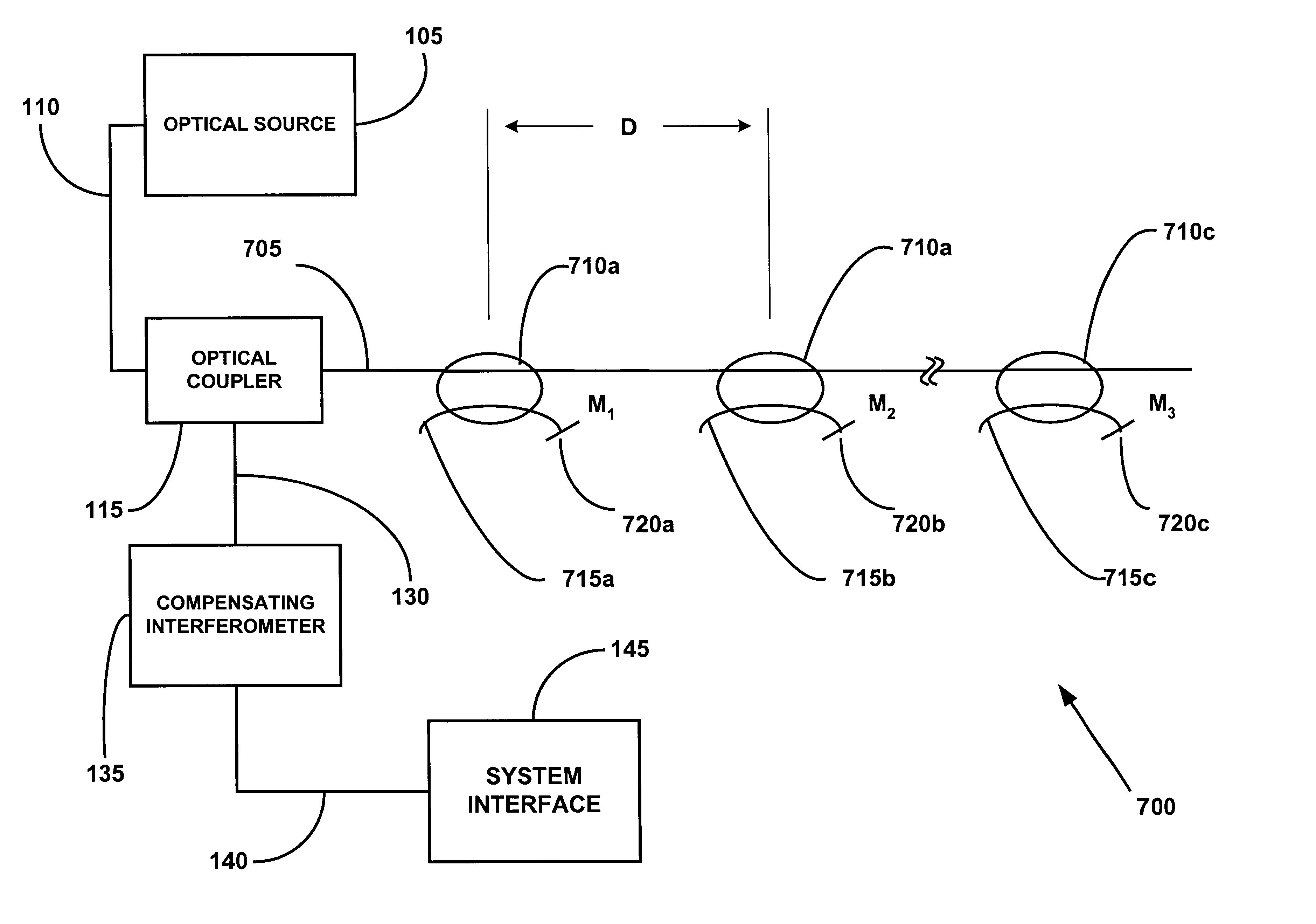
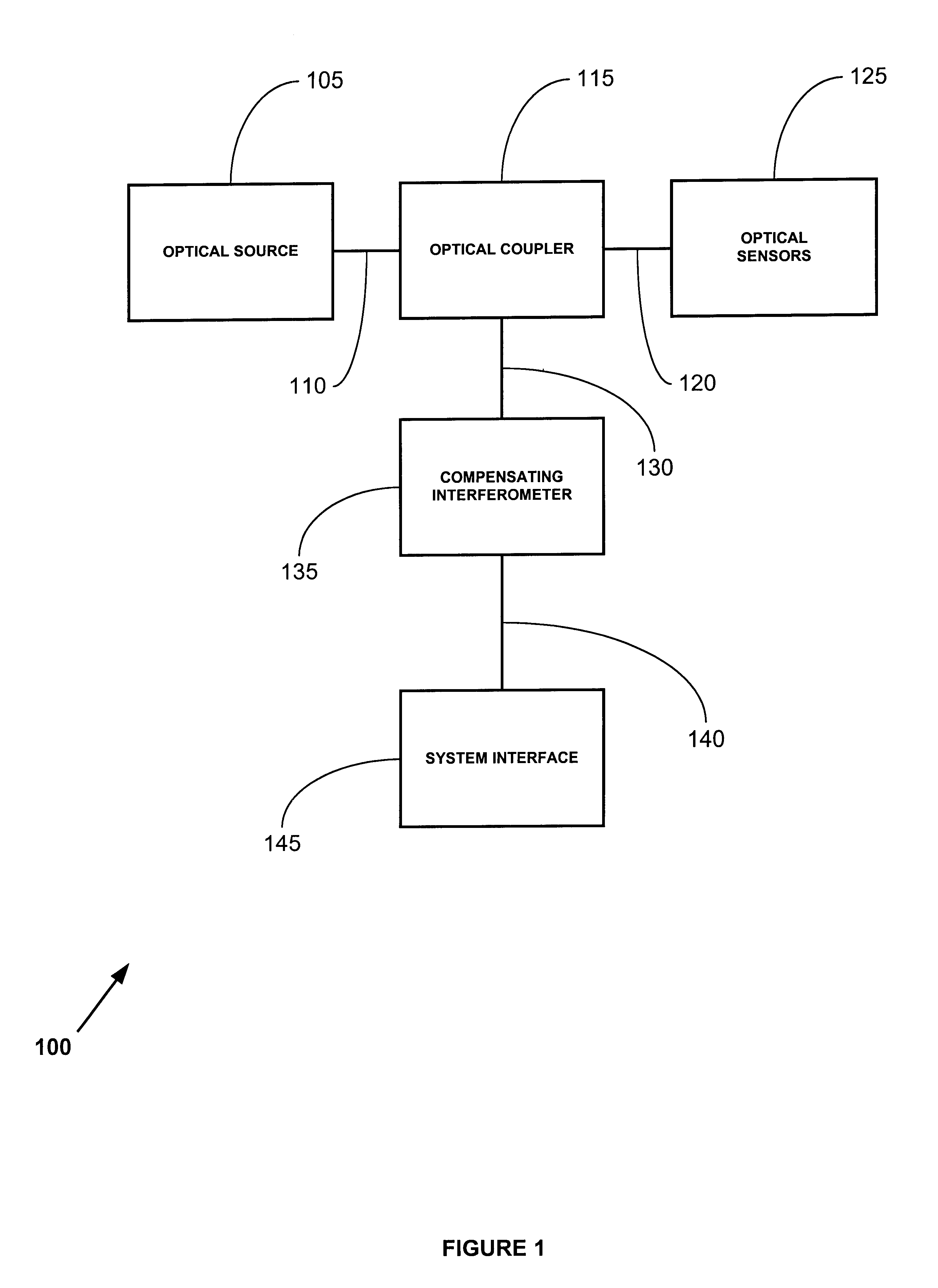
Referring initially to FIG. 1, an embodiment of an optical sensing system 100 preferably includes an optical source 105, an optical conductor 110, an optical coupler 115, an optical conductor 120, optical sensors 125, an optical conductor 130, a compensating interferometer 135, a communication interface 140, and a system interface 145.

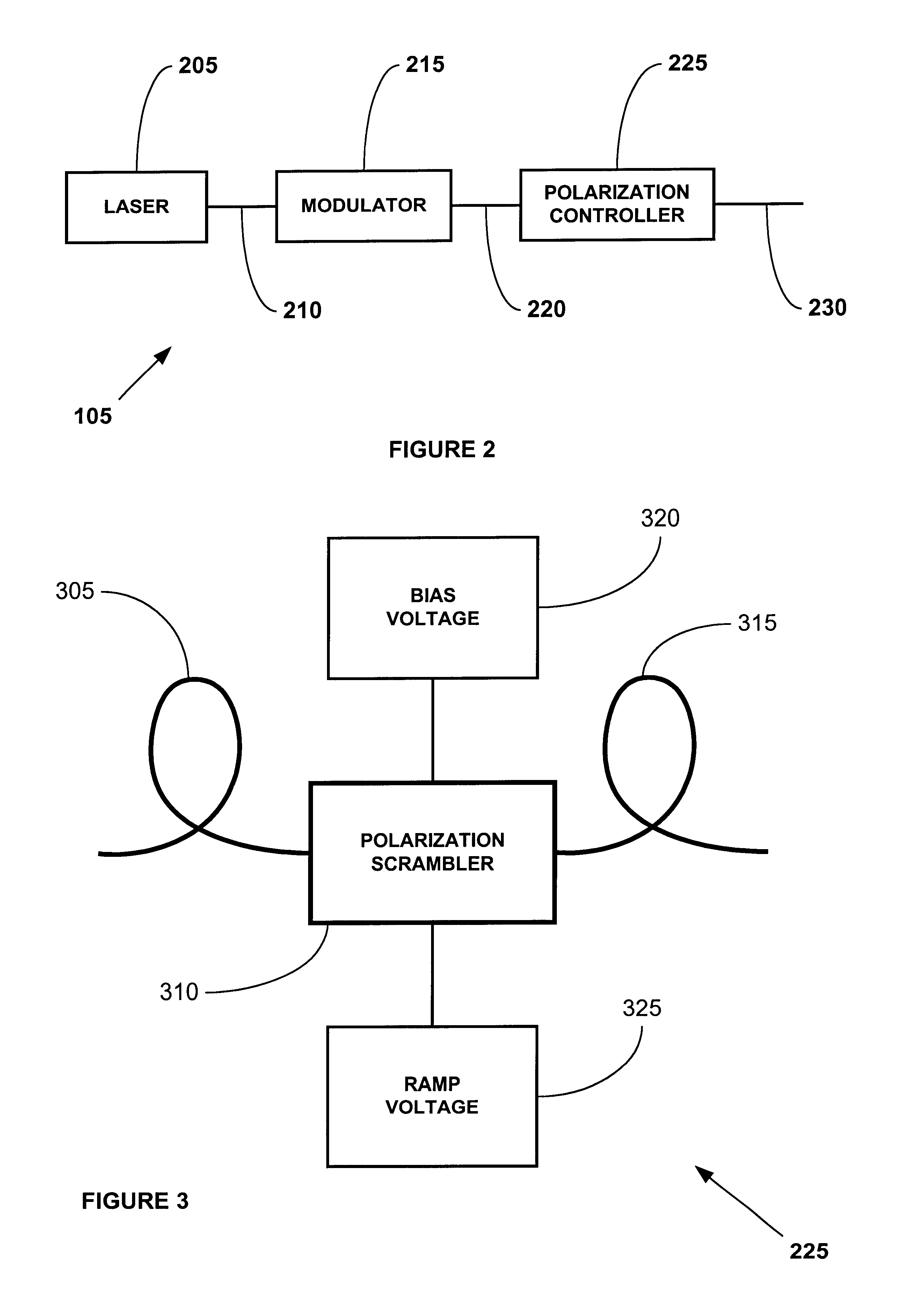
The optical source 105 preferably controllably generates light waves having a predetermined wavelength distribution. The optical source 105 is preferably coupled to the optical conductor 110. Referring to FIG. 2, in a preferred embodiment, the optical source 105 includes a laser 205, an optical conductor 210, an optical modulator 215, an optical conductor 220, a polarization controller 225, and an optical conductor 230.

The laser 205 preferably controllably generates coherent light waves having a predeterm...


PUM


Abstract

A fiber optic acoustic sensor system including an optical conductor having low reflectivity mirrors is provided. Optical sensors are provided by sections of the optical conductor bounded by pairs of the low reflectivity mirrors. Pulses of light are injected into the optical conductor and reflected by the low reflectivity mirrors. The reflected pulses of light are processed using a compensating interferometer to generate interference patterns representative of the environmental conditions acting upon the optical conductor.

Description

BACKGROUND OF THE INVENTIONThis invention relates to fiber optic sensors and, more particularly, to marine seismic streamers using optical fibers for sensing changes in acoustic fields.Marine seismic sensing devices are known that utilize discrete optical hydrophones which are assembled into marine seismic streamers. The discrete hydrophones use a pulsed laser to provide light to hydrophones made of optical fiber wound around mandrels. Pressure changes about a hydrophone cause deformations, which in turn cause phase modulation of light traveling through the fibers within each discrete hydrophone. Those changes are recorded as interference patterns produced at each discrete sensor. The individual interference patterns are coupled to a return cable to return to the shipboard for processing. Discrete optical hydrophones require a significant amount of fabrication, because each hydrophone must be spliced to optical coupler and return fibers, and the whole assembly encased and inserted i...

Claims


Application Information

Patent Timeline
Patent Type & Authority Patents(United States)
IPC IPC(8): G01H3/00G01H9/00G01V1/16G01V1/20
CPCG01H3/005G01H9/004G01V1/201
Inventor SIEMS, LEE E.CHOI, HAN-SUNKNAPP, GREYSONKANDERS, REINISMAIDA, JOHN L.O'BRIEN, TOM
Owner ION GEOPHYSICAL CORP
Why Eureka
Try Eureka