Exhaust gas purifying catalyst

a technology of exhaust gas and purifying catalyst, which is applied in the direction of physical/chemical process catalysts, arsenic compounds, separation processes, etc., can solve the problems of heterogeneous crystal structure of solid solutions, high cost, and high cost of catalysts

Inactive Publication Date: 2003-08-05
UMICORE SHOKUBAI JAPAN CO LTD +1
View PDF7 Cites 23 Cited by
  • Summary
  • Abstract
  • Description
  • Claims
  • Application Information

AI Technical Summary

Benefits of technology

According to this invention, carbon monoxide, hydrocarbon, and nitrogen oxide, which are contained in the exhaust gas emitted from the internal combustion engine such as the gasoline engine in an automobile, are simultaneously removed. Further, the catalyst of this invention excels in heat resistant property and durability because it comprises zirconium oxide containing cerium and lanthanum.

Problems solved by technology

This method indeed excels in the ability to purify the exhaust gas immediately after the start of the engine but yet entails the disadvantage that it requires a catalyst having a higher heat resistant property because it is used in the proximity of the engine and exposed to a higher temperature than ever.
In this circumstance, the conventional catalysts do not fully meet the demand for the heat resistant property.
In the conventional oxygen storage materials, however, when cerium oxide or lanthanum oxide are doped in zirconium oxide, the components does not fully dope and thereby give birth to independent cerium oxide and the like, with the result that the produced solid solution assumes a heterogeneous crystal structure.
If this amount drops below 0.05 g, the shortage will be at a disadvantage in manifesting no sufficient catalytic activity.
Conversely, if the amount exceeds 30 g, the excess will be at a disadvantage in bringing no proportionate addition to the catalytic activity.
If this amount drops below 10 g, the shortage will be at a disadvantage in not enabling the noble metal to be sufficiently dispersed and preventing the produced catalyst from acquiring sufficient durability.
Conversely, if this amount exceeds 300 g, the excess will be at a disadvantage in adding to the pressure loss of the exhaust gas.
If this amount drops below 0.1 g, the shortage will be at a disadvantage in that the catalyst containing Pd manifests only insufficient heat resistant property.
Conversely, if the amount exceeds 50 g, it will be at a disadvantage in not bringing any additional performance proportionate to the excess.
If this amount drops below 5 g, the shortage will be at a disadvantage in that the catalyst suffers deficiency in durability and OSC (Oxygen Storage Component) capacity.
Conversely, if the amount exceeds 250 g, the excess will be at a disadvantage in increasing the pressure loss of the exhaust gas.

Method used


Image

  • Exhaust gas purifying catalyst
  • Exhaust gas purifying catalyst
  • Exhaust gas purifying catalyst

Examples


referential example

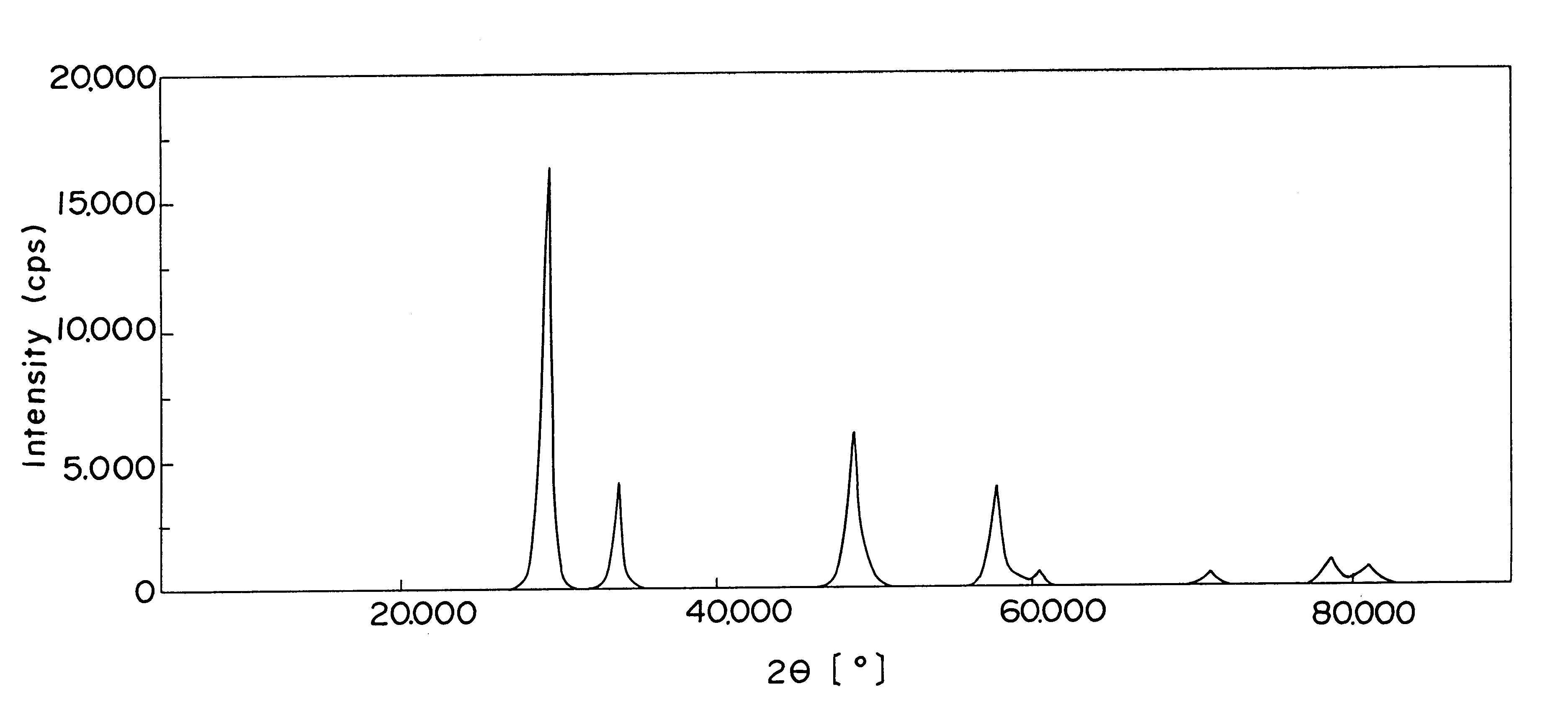
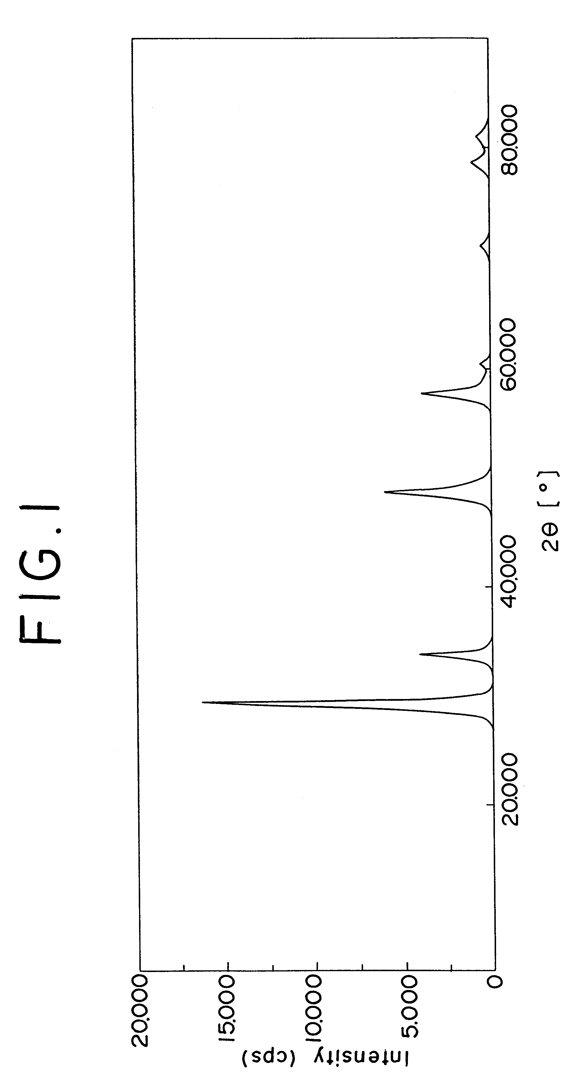
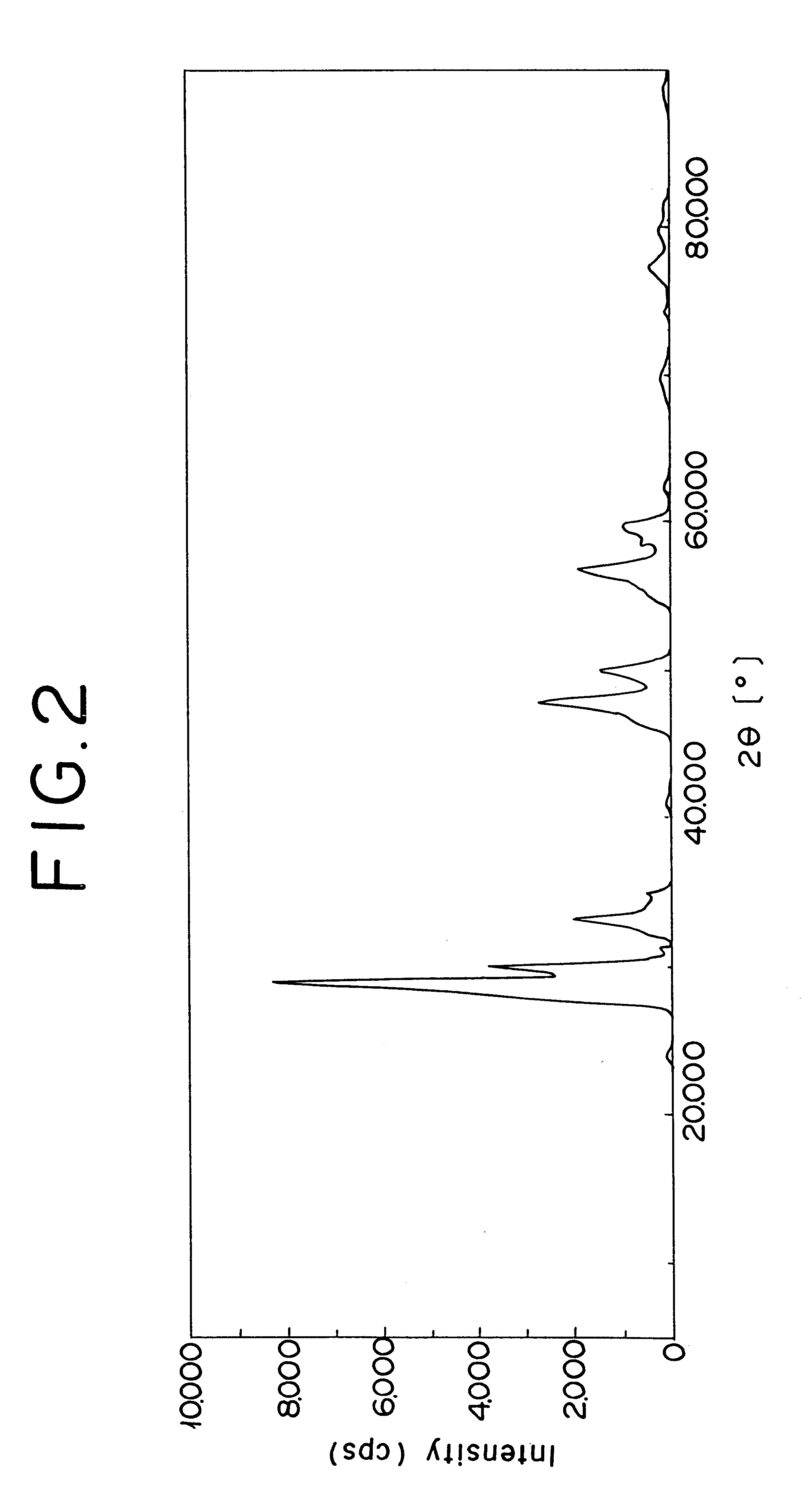
FIG. 1 shows the spectrum pattern, produced by the X-ray diffraction, of the zirconium oxide containing cerium and lanthanum in this invention, and FIG. 2 the spectrum pattern of the conventional zirconium oxide containing cerium and lanthanum. In FIG. 2, it is noted that the conventional oxide revealed the peaks of various independent oxides including cerium oxide. In FIG. 1, it is noted that the oxide used in Example 1 revealed only a peak of the tetragonal crystal structure of zirconium oxide. Other oxides of the present invention also reveal same results as in FIG. 1. Such oxides were evaluated after each the samples had been aged in air at 1000.degree. C. for 10 hours.

Next, the zirconium oxide containing cerium and lanthanum in this invention and the conventional zirconium oxide containing cerium and lanthanum are compared in the amount of oxygen stored that expresses the ability to adsorb and desorb oxygen. The results are shown in Table 1.

It is clear from Table 1 that the oxi...

example 1

A zirconium-cerium-lanthanum composite oxide (Powder A1) was obtained by hydrolyzing a zirconium oxychloride solution thereby obtaining zirconium hydroxide, adding an aqueous nitric acid solution of cerium and lanthanum to the zirconium hydroxide and mixing them together, neutralizing the resultant mixture by addition of an alkali, washing, drying at 120.degree. C. for two hours and calcining at 700.degree. C. for one hour the product of neutralization, with the relevant components used in amounts calculated to form a weight ratio of 40 g of zirconium oxide, 20 g of cerium oxide, and 15 g of lanthanum oxide.

A quantity of 40 g of Powder A1 was impregnated with an aqueous palladium nitrate solution containing 2 g of palladium. Thereafter, the impregnated composite oxide was dried thoroughly at 150.degree. C. and then calcined at 500.degree. C. for one hour to obtain a palladium-containing zirconium-cerium-lanthanum composite oxide (Powder B1).

Separately, 30 g of alumina (.gamma.-Al.su...

example 2

A zirconium-cerium-lanthanum composite oxide (Powder A2) was obtained according to the procedure of Example 1 while changing the amounts of zirconium oxychloride, cerium, and lanthanum to be used so as to form a weight ratio of 25 g of zirconium oxide, 12.5 g of cerium oxide, and 9.5 g of lanthanum oxide.

Next, a palladium-containing zirconium-cerium-lanthanum composite oxide (Powder B2) was obtained according to the procedure of Example 1 while using 47 g of Powder A2 instead of 40 g of Powder A1.

In a ball mill, 49 g of Powder B2, 103 g of alumina (.gamma.-Al.sub.2 O.sub.3) having a specific surface area of 150 m.sup.2 / g, 10 g equivalent of barium hydroxide as an oxide, 5 g of acetic acid, and 150 g of deionized water were ball milled for 15 hours to form a water slurry. A monolithic carrier (supra) was coated with the slurry as in Example 1 to obtain catalyst 2.


PUM

PropertyMeasurementUnit
temperatureaaaaaaaaaa

Abstract

An exhaust gas purifying catalyst having a refractory three-dimensional structure coated with a catalytically active component comprising at least one kind of noble metals, a refractory inorganic oxide, and a zirconium oxide containing cerium and lanthanum, the crystal structure of the zirconium oxide containing cerium and lanthanum being a tetragonal structure of zirconium oxide.

Description

1. Field of the InventionThis invention relates to an exhaust gas purifying catalyst for simultaneous removal of carbon monoxide (CO), hydrocarbon (HC), and nitrogen oxides (NO.sub.X), which are harmful component contained in the exhaust gas from an internal combustion engine, and a method for the purification of exhaust gases by the use of the catalyst.2. Description of Related ArtVarious inventions have been proposed concerning the exhaust gas purifying catalyst for removing harmful components contained in the exhaust gas emitted from the internal combustion engine (JP-A-7-60117).In recent years, various studies including the improvement of an engine itself are now under way with a view to complying with the global trend toward intensification of the regulations on the exhaust gas. One of the most leading methods is to expedite the ignition of a catalyst by approximating the position of the catalyst closely to the engine side thereby enabling the temperature of the catalyst bed im...

Claims


Application Information

Patent Timeline
Patent Type & Authority Patents(United States)
IPC IPC(8): B01J23/63B01D53/94B01J23/58B01J23/54B01J21/06
CPCB01D53/945B01J23/58B01J23/63Y02T10/22Y02T10/12B01D53/94B01J21/06
Inventor TANIGUCHI, SHIGEYOSHIHORIUCHI, MAKOTO
Owner UMICORE SHOKUBAI JAPAN CO LTD
Why Eureka
Try Eureka