

Low-pressure gas discharge lamp with a copper-containing gas filling
a low-pressure gas and gas filling technology, which is applied in the direction of low-pressure discharge lamps, gas-filled discharge tubes, solid cathodes, etc., can solve the problems of energy difference being converted into undesirable thermal radiation, primarily emitting radiation in the high-, invisible uv-c range of electromagnetic spectrum, etc., to achieve high visual efficiency of lamps and reduce power consumption. , the effect of reducing the effect of power consumption
Inactive Publication Date: 2003-08-05
KONINKLIJKE PHILIPS ELECTRONICS NV
View PDF4 Cites 16 Cited by
- Summary
- Abstract
- Description
- Claims
- Application Information
AI Technical Summary
Benefits of technology
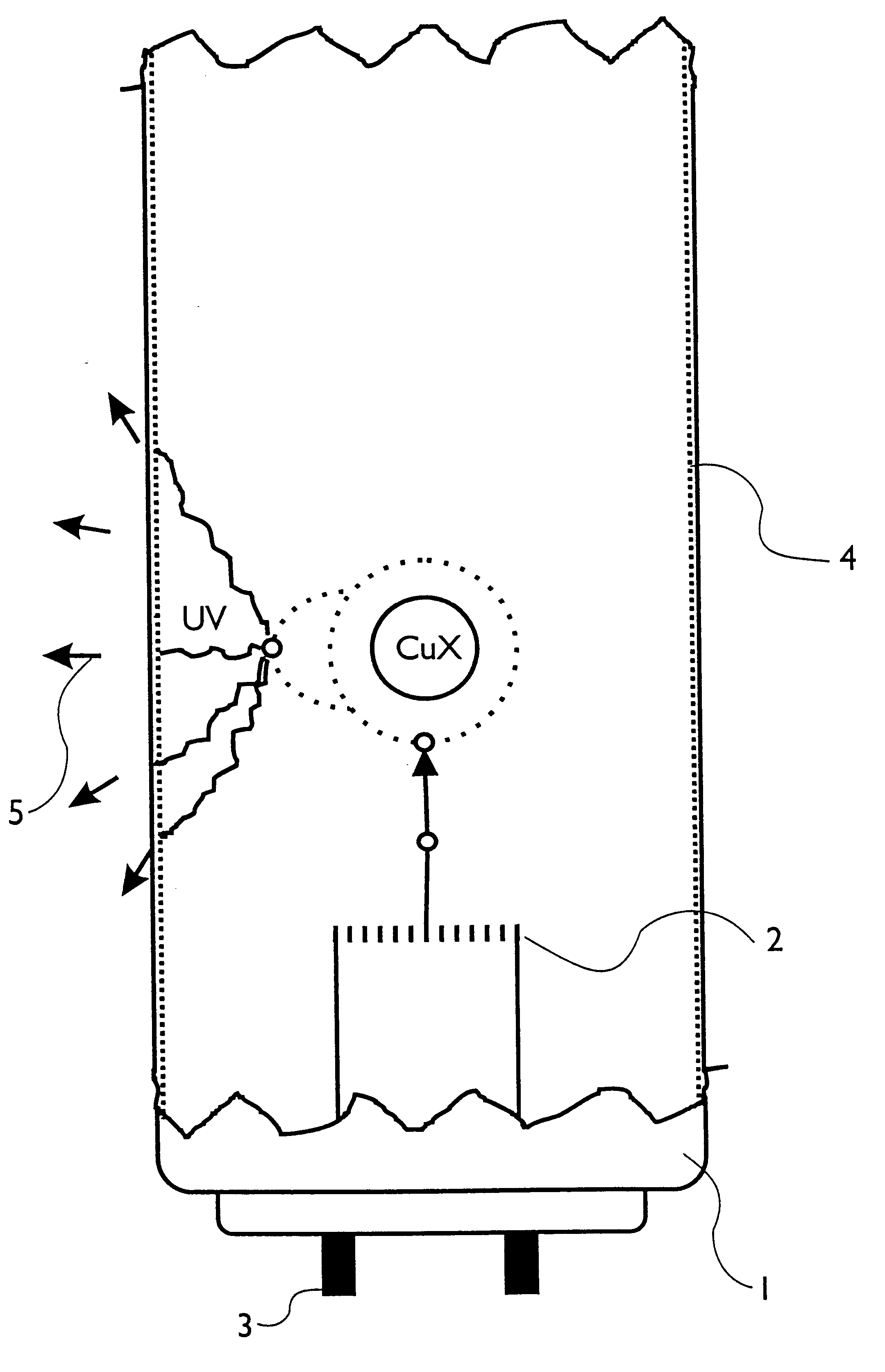
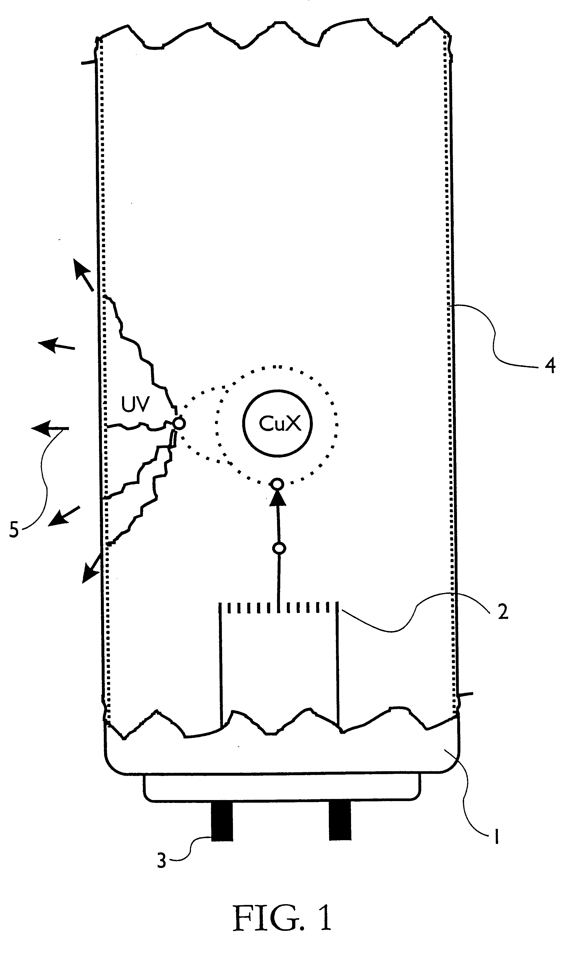
In the lamp in accordance with the invention, a molecular gas discharge takes place at a low pressure, which gas discharge emits radiation in the visible and near UVA region of the electromagnetic spectrum. Apart from the characteristic lines of copper at 325, 327, 510, 570 and 578 nm, said radiation also includes a wide continuous spectrum in the blue range of the electromagnetic spectrum from 400 to 550 nm. As this radiation originates from a molecular discharge, the type of copper compound, possible further additives as well as the internal pressure of the lamp and the operating temperature enable the exact position of the continuous spectrum to be controlled.
In combination with phosphors, the lamp in accordance with the invention has a visual efficiency which is substantially higher than that of conventional low-pressure mercury discharge lamps. The visual efficiency, expressed in lumen / Watt, is the ratio between the brightness of the radiation in a specific visible wavelength range and the energy for generating the radiation. The high visual efficiency of the lamp in accordance with the invention means that a specific quantity of light is obtained at a smaller power consumption. Besides, the use of mercury is avoided.
A further improved efficiency at lower operating temperatures is achieved if the gas filling comprises a mixture of a copper compound selected from the group formed by the halogenides, oxides, chalcogenides, hydroxides, hydrides and the metalorganic compounds of copper with a copper halogenide.
Problems solved by technology
A drawback of the mercury low-pressure gas discharge lamps resides in that mercury vapor primarily emits radiation in the high-energy, yet invisible UV-C range of the electromagnetic spectrum.
In this process, the energy difference is converted to undesirable thermal radiation.
This results in a simplification of the manufacturing process.
Method used
View moreImage
Smart ImageViewing Examples

Examples
Embodiment Construction
A cylindrical discharge vessel made from a type of glass that is transparent to UVA radiation, having a length of 15 cm and a diameter of 2.5 cm, is provided with electrodes of tungsten. The discharge vessel is evacuated and simultaneously a dose of 3 .mu.g / cm.sup.3 copper(I) oxide, 3 .mu.g / cm.sup.3 copper(I) bromide and 3 .mu.g thallium(I) bromide is added. Also argon is introduced at a partial pressure of 10 mbar.
An alternating current originating from an external alternating current source is supplied and, at an operating temperature of 420.degree. C., a lumen efficiency of 85 lm / W is measured.
Login to View More PUM
 Abstract
A low-pressure gas discharge lamp having a gas discharge vessel containing a gas filling including a copper compound. The copper compound is selected from the oxides, chalcogenides, hydroxides, hydrides and the metalorganic compounds of copper. In addition to the copper compound, the gas filling includes a buffer gas such as argon, and may also include a thallium compound and / or a copper halogenide.
Description
The invention relates to a low-pressure gas discharge lamp comprising a gas discharge vessel with a copper-containing gas filling, electrodes and means for generating and maintaining a low-pressure gas discharge.BACKGROUND AND SUMMARYLight generation in low-pressure gas discharge lamps is based on the principle that charge carriers, particularly electrons but also ions, are accelerated so strongly by an electric field between the electrodes of the lamp that collisions with the gas atoms or molecules in the gas filling of the lamp cause these gas atoms or molecules to be excited or ionized. When the atoms or molecules of the gas filling return to the ground state, a more or less substantial part of the potential energy is converted to radiation.Conventional low-pressure gas discharge lamps comprise mercury in the gas filling and, in addition, a phosphor coating on the inside of the gas discharge vessel. A drawback of the mercury low-pressure gas discharge lamps resides in that mercur...
Claims
Login to View More Application Information
Patent Timeline
 Patent Type & AuthorityPatents(United States)
IPC IPC(8): H01J61/00H01J61/16H01J61/12H01J61/70
CPCH01J61/125H01J61/16H01J61/70
InventorHILBIG, RAINERSCHOLL, ROBERT PETERKOERBER, ACHIMBAIER, JOHANNES
OwnerKONINKLIJKE PHILIPS ELECTRONICS NV