Active signal conditioning circuitry for well logging and monitoring while drilling nuclear magnetic resonance spectrometers

a technology of active signal and well logging, which is applied in the direction of reradiation, measurement using nmr, instruments, etc., can solve the problems of circuit saturation, circuitry saturation, and protection of receiver circuitry, and achieve the most severe "electronic" dynamic range design problems, circuitry saturation,

Inactive Publication Date: 2003-08-05
BAKER HUGHES INC
View PDF4 Cites 60 Cited by
  • Summary
  • Abstract
  • Description
  • Claims
  • Application Information

AI Technical Summary

Problems solved by technology

The combination of these two factors--same transmit and receive signal frequencies and such an enormous disparity between the excitation and response voltages creates well known receiver circuitry protection and signal-to-noise ratio design problems.
A combined transmitter / receiver antenna circuit, however, exhibits the most severe "electronic" dynamic range design problems.
If such a transmitter voltage is directly applied to the small signal receiver circuitry without an adequate protection, the circuitry would be saturated during the transmission pulse and then might require an inordinately long "dead" time for recovering after the primary RF pulse has been removed.
Furthermore, if not properly protected, this relatively large transmission voltage could irreversibly damage the receiver circuitry.
The attenuator has been designed to produce a high band pass signal attenuation during the RF field transmission, however, it might undesirably shrink the relatively miniscule response voltages in the receive mode, as well.
Moreover, if the attenuator is somewhat noisy, its parasitic signals could be coupled back into the resonant tank circuit and their energy maybe enough to induce undesirable tank self-oscillations.
These oscillations, being within the same frequency range as the input signal, would interfere with the acquired response from the formation apparently reducing the signal-to-noise ratio (SNR).
In reality, a practical assembly will always contain some undesirable electromagnetic coupling between these two antennas: it could be capacitive or magnetic or, which happens more often, of both kinds.
As the result of this unavoidable coupling the induced voltage in the receiver antenna associated with the transmission pulse can still be sufficiently large to saturate or even damage electronic components in the receiver circuitry.
Moreover, there is a significant difference between the capabilities of common laboratory NMR spectrometers and downhole NMR spectrometers.
In well logging and monitoring while drilling NMR applications, however, NMR spectrometers necessarily operate with multiple and lower frequencies and must be functional within a wide range of temperatures that immediately results in less stable antenna and attenuator electrical parameters.
There are two difficulties encountered in employing a hard synchronization for an imperfectly tuned tank.
The first one is associated with elevated tool power consumption, that is, the further apart the driver's synch and tank's resonance frequencies, the lower actual tank's electrical quality, its effective impedance and higher the driver output current.
The second problem appears in the receiver mode where the formation response has a frequency exactly equal to the driver's frequency response.
As it has been mentioned above, the most severe problem in NMR well logging apparatus appears when the attenuator has been designed as tunable.
Thus, due to the abovementioned temperature influences it becomes difficult to keep attenuator tuning exactly matched to the transmitter antenna driver's frequency because its parameters change along with changes in temperature and pressure down hole.
Changing the attenuator tuning will inevitably reduce its stop-band losses and result in elevating the voltage at the input of receiver circuitry that might exceed a safe level.
These, however, would result in unreasonable and often non-achievable stability requirements and introduce additional noise.
On other hand, semiconductor voltage controlled capacitors, or varicaps, are impractical due to their low initial capacitance and small voltages that such a device can withstand.
However, even if these design constraints were overcome, the attenuator tuning requirements would also deteriorate the NMR tool logging speed that is associated with the time required to accomplish tuning.

Method used


Image

  • Active signal conditioning circuitry for well logging and monitoring while drilling nuclear magnetic resonance spectrometers
  • Active signal conditioning circuitry for well logging and monitoring while drilling nuclear magnetic resonance spectrometers
  • Active signal conditioning circuitry for well logging and monitoring while drilling nuclear magnetic resonance spectrometers

Examples


Embodiment Construction

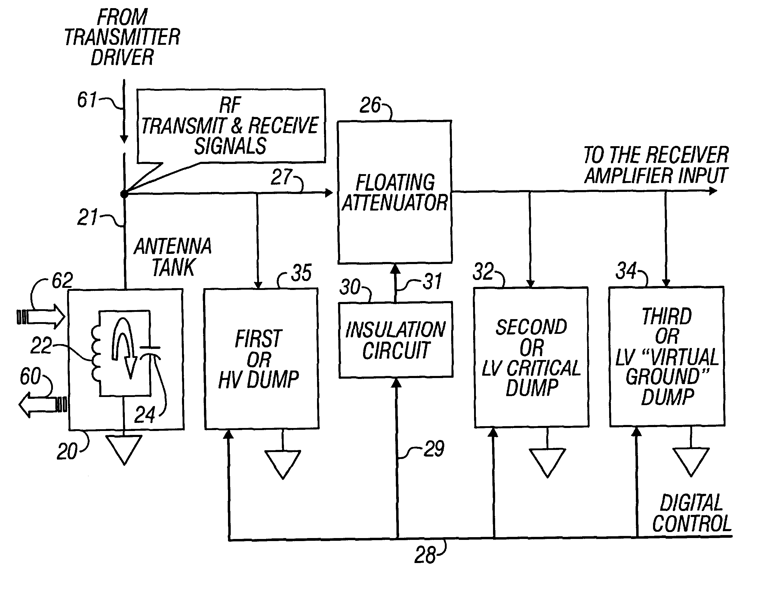
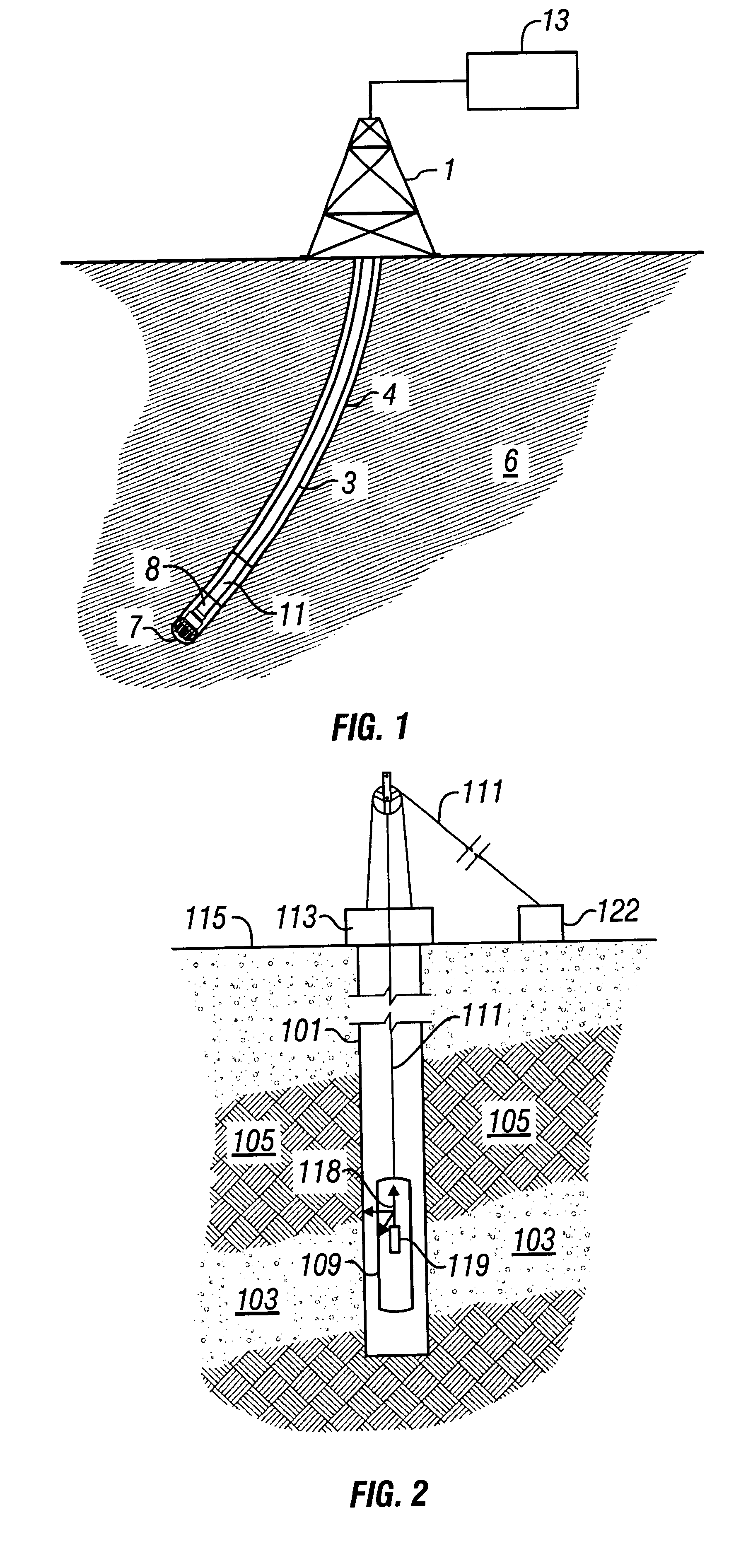
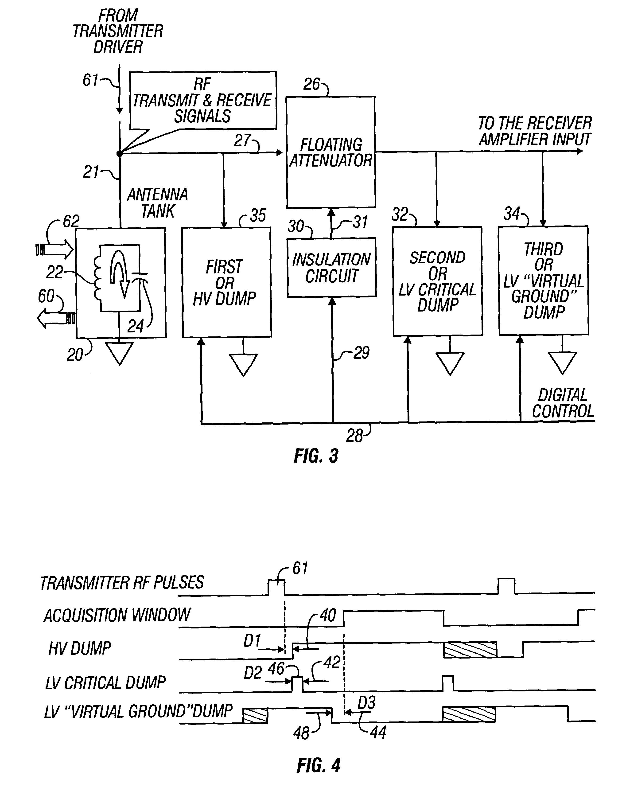
A drilling operation environment for deployment down hole of an NMR tool according to the present invention is shown deployed in a monitoring while drilling environment in FIG. 1. As shown in FIG. 1, a drill rig 1 drives a drill string 3 that, which typically is comprised of a number of interconnecting sections. A down hole assembly 11 is formed at the distal end of the drill string 3. The down hole assembly 11 includes a drill bit 7 that advances to form a bore 4 in the surrounding formation 6. A portion of the down hole assembly 11, incorporating an electronic system 8. The electrical system 8 may, for example, provide information to a data acquisition and analysis system 13 located at the surface. The electrical system 8 includes one or more nuclear magnetic resonance (NMR) tools. The NMR tool includes a NMR spectrometer, which is well known in the art. The electrical system comprising the NMR tool and spectrometer further comprise the active signal conditioning circuitry for the...


PUM


Abstract

NMR transmitter / receiver antenna active signal conditioning circuitry that enables receiver antenna circuit protection from high voltage RF transmitter pulses, provides energy dumping for the entire antenna in successive stages and eliminates re-tuning during sweeping of the antenna frequency.

Description

The present invention is related to the field of nuclear magnetic resonance ("NMR") sensing tools deployed in down hole well logging and monitoring while drilling environments. More specifically, the invention is related to a NMR well logging and monitoring while drilling tool that comprises an active antenna signal conditioning circuitry for providing multi-frequency measurements and respective suppression of noise.DESCRIPTION OF THE RELATED ARTNMR well logging instruments are utilized for determining properties of earth formations including: the fractional volume of pore space, the fractional volume of mobile fluid filling the pore space and other petrophysical parameters. An NMR well logging instrument typically contains a permanent magnet to produce a static magnetic field in adjacent earth formations. The NMR well logging instrument typically includes a transmitting antenna assembly positioned near the magnet. The transmitting antenna assembly is shaped so that a pulse of radio...

Claims


Application Information

Patent Timeline
Patent Type & Authority Patents(United States)
IPC IPC(8): G01V3/32G01R33/36G01R33/32G01V3/18G01R33/44
CPCG01N24/081G01R33/36G01V3/32
Inventor FORGANG, STANISLAV W.KRUGLIAK, ZINOVY B.
Owner BAKER HUGHES INC
Why Eureka
Try Eureka