Ultrasonic sealer

a technology of ultrasonic sealing and sealing apparatus, which is applied in the direction of soldering apparatus, manufacturing tools,auxillary welding devices, etc., can solve the problems of aluminum foil not being applied to heat sealing apparatus using high-frequency coils, aluminum foil being difficult to recycle,

Inactive Publication Date: 2003-08-12
SHIKOKU KAKOOKI CO LTD
View PDF26 Cites 58 Cited by
  • Summary
  • Abstract
  • Description
  • Claims
  • Application Information

AI Technical Summary

Problems solved by technology

In the future it is considered that a packing container using a packing material comprising a laminate of thermoplastic having no aluminum foil will be the mainstream, since recycling treatment of packing material laminate including aluminum foil is considered difficult after containers are disposed.
However, for heat sealing a packing material comprising a laminate of thermoplastic including no aluminum foil, a heat sealing apparatus using a high-frequency coil which has been used with packing materials including aluminum foil cannot be applied, so it is necessary to use other heat sealing apparatuses such as an ultrasonic sealing apparatus, for example.
However, the ultrasonic sealing apparatuses, which have well-known properties and which have been generally used, require a larger space for the apparatus when enhancing the heat sealing ability and there is a drawback that such apparatus cannot be set on a sealing jaw of a transverse sealing apparatus of the filling / packing machine.
Additionally, uniformly heat sealing the elongated entire face at both end portions has been considered difficult with the known ultrasonic apparatuses used for a sealing jaw of the transverse sealing apparatus of a filling / packing machine, because one converter is used and the dimension of the motional amplitude at the sealing face of the horn (output surface) reduces with increasing lateral distance away from the central area where the converter is coupled to the horn.
Further, it is possible to form the horn and the fixtures uninterruptedly on which uninterrupted body plural converters may be erected.
Without a control means, the vibration becomes non-uniform and there is a possibility that a seal with uniform and suitable strength on the sealing face will not be, obtained.

Method used


Image

  • Ultrasonic sealer
  • Ultrasonic sealer
  • Ultrasonic sealer

Examples


Embodiment Construction

The preferable examples of embodiments of an ultrasonic sealing apparatus of the present invention are described according to the drawings in the following, while the present invention is not limited to the description in the drawings.

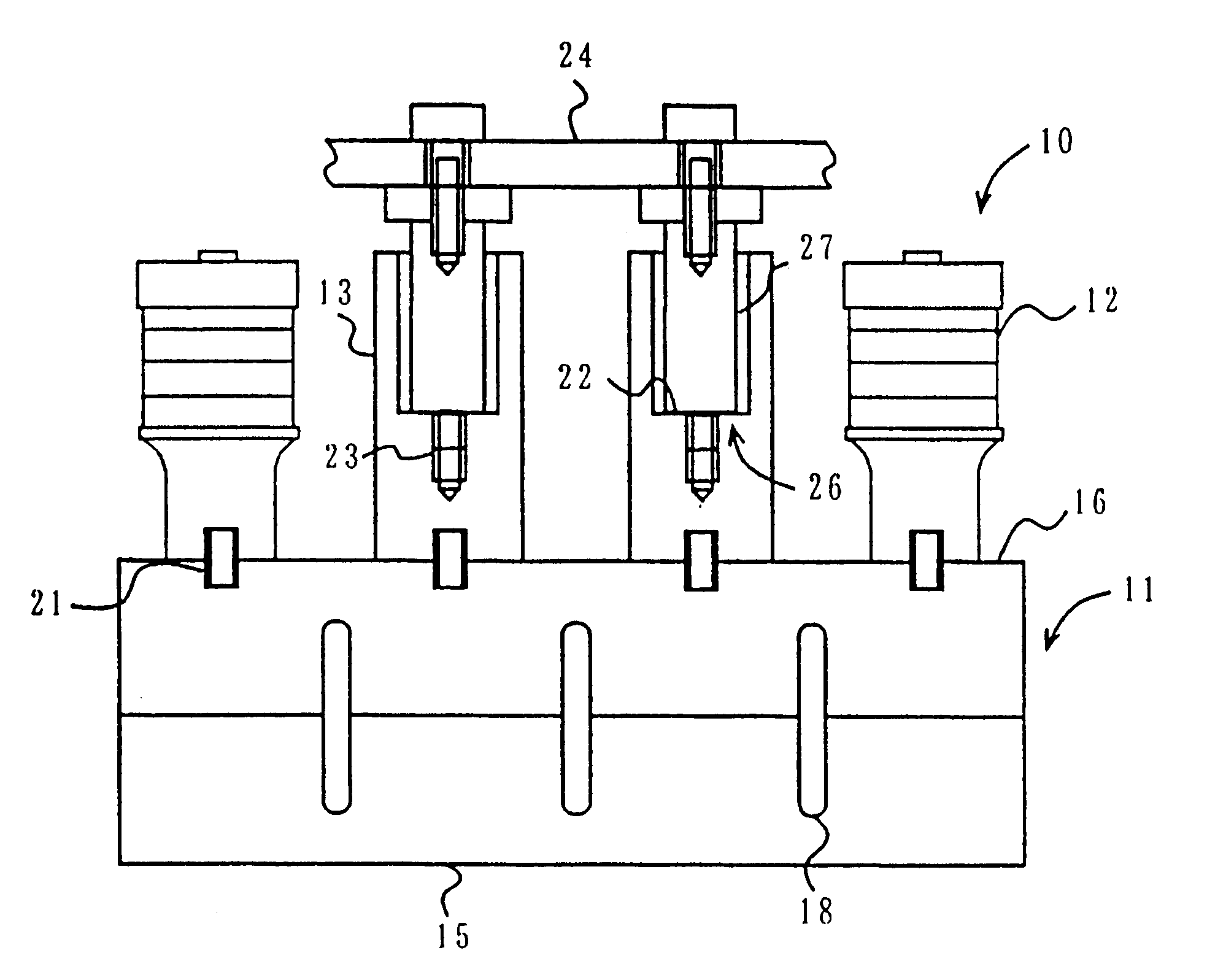
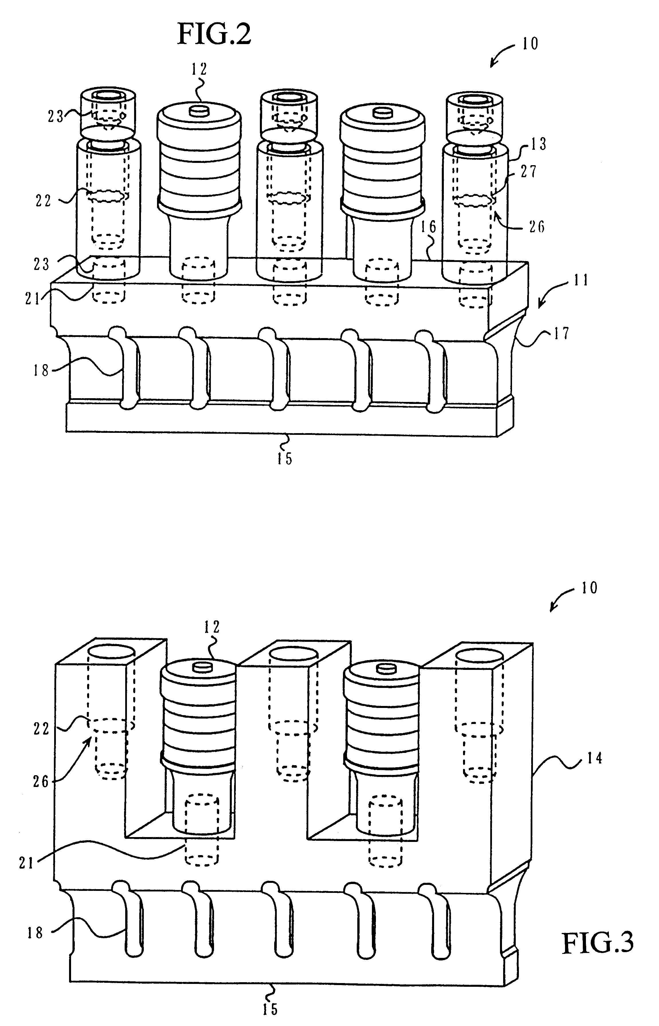
FIG. 2 is a schematic perspective view of an ultrasonic sealing apparatus 10 of the present invention. Additionally, in FIG. 2 to FIGS. 9, 10 shows an which includes a horn 11; a converter 12; a fixture 13; a horn-fixture uninterruptedly formed body 14; a sealing face 15 of the horn 11; a flat face 16 of the horn 11; a curved portion 17 of the horn 11; a slot 18; a slit 19; a collar 20; a stud bolt 21; a receiving face 22 of stud attachment; a female screw portion 23; a sealing jaw 24; a damper fixing 25; a nodal plane 26; a stud attachment 27; and an attaching flange 28, respectively.

With reference to FIG. 2, the ultrasonic sealing apparatus 10 of the present invention is shown in which two converters 12 and three fixtures 13 are erected on the horn 1...


PUM

PropertyMeasurementUnit
longitudinal wave sonic speedaaaaaaaaaa
sonic speedaaaaaaaaaa
thicknessaaaaaaaaaa

Abstract

An ultrasonic sealing apparatus comprises at least one horn having an elongated sealing face for sealing a packing material. Plural converters are erected on a side of the horn opposite to the sealing face for resonating the horn with a vibrating frequency. The ultrasonic sealing apparatus has a length that is one wavelength of the vibrating frequency and is fixed in position to a sealing jaw at a nodal plane of the vibrating frequency.

Description

1. Technical FieldThe present invention relates to an ultrasonic sealing apparatus provided with an elongated sealing face for sealing a packing material, specifically a tubular packing material filled with content such as a liquid beverage, and more particularly to an ultrasonic sealing apparatus having at least one horn and plural converters and to a transverse sealing apparatus provided with the ultrasonic sealing apparatus.2. Background ArtHitherto, there has been known a packing machine in which a sterilized packing material web is used for a rectangular parallelepiped packing container filled with juice, etc. as shown in FIG. 1 see also (Japanese Patent Publication No. 23368 / 1989). In brief, the filling / packing machine as a whole comprises a reel 2 supporting a packing material web 1 in a rolled state, a sterilization, device 3 for sterilizing the tabular packing material web successively unwound from the reel 2, a longitudinal sealing section 4 for sealing the longitudinal ed...

Claims


Application Information

Patent Timeline
Patent Type & Authority Patents(United States)
IPC IPC(8): B29C65/08B65B51/26B65B51/22
CPCB29C65/08B29C66/849B65B51/225B65B51/26B29C66/1122B29C66/4312B29C66/8145B29C66/8167B29C65/085B29C66/9513B29C66/8322B29C66/81411B29C66/9517B29C66/83543B29C66/4322B29C66/73921B29C66/71B29C66/72321B29C66/72328B29C66/7234B29K2023/06
Inventor SHINOHARA, MITSUHIKOISEKI, TAKESHIUEDA, MICHIOKUME, SATOSHITAMAMOTO, OSAMUHAMAGUCHI, TADAYOSHI
Owner SHIKOKU KAKOOKI CO LTD
Why Eureka
Try Eureka