Independent regulation of multiple outputs in a soft-switching multiple-output flyback converter

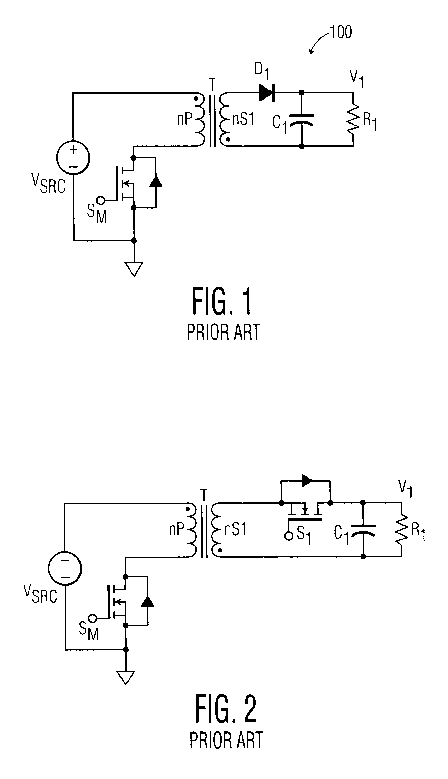
a flyback converter and multiple output technology, applied in the field of dctodc converters, can solve the problems of high bandwidth feedback loop, unstable operation of the flyback converter 100, and high frequency feedback loop

Inactive Publication Date: 2003-08-12
KONINKLIJKE PHILIPS ELECTRONICS NV
View PDF7 Cites 50 Cited by
  • Summary
  • Abstract
  • Description
  • Claims
  • Application Information

AI Technical Summary

Benefits of technology

Advantages of the present invention include simultaneous soft-switching of the primary-side and secondary-side switches, and higher circuit efficiency as a consequence of using bi-directional switches in the output circuits instead of diodes resulting in lower circuit losses especially in low-voltage, high current applications.

Problems solved by technology

One disadvantage of the flyback converter 100 is that when operated in the CCM, the flyback converter 100 may exhibit potentially unstable operation when used with high bandwidth feedback loops.
That is, the converter 100 is susceptible to oscillations when high bandwidth feedback loops are used.
Another disadvantage of this circuit topology is that the diode D.sub.1 is hard-switched.
A drawback of circuit 310 is that when the circuit operates in the discontinuous conduction mode, it is necessary to drain the transformer T of energy in each cycle.
This may be problematic in that the unidirectional switch associated with the last or final output circuit in the switching cycle (e.g., switch S.sub.2) has to remain `on` for a long enough time to fully drain the transformer T in each switching cycle.
However, even though the illustrative prior art topology of FIG. 4 enables synchronous rectification and soft switching, it shares the drawback or restriction, common to all the prior art circuits illustrated, in that the last output (e.g., output V.sub.2 in FIG. 4) has to be cycled last in each energy cycle.
From a control or circuit standpoint, this restriction may not always be desirable.
While this is easily achieved, it is an undesirable situation for a fly-back configuration.

Method used


Image

  • Independent regulation of multiple outputs in a soft-switching multiple-output flyback converter
  • Independent regulation of multiple outputs in a soft-switching multiple-output flyback converter
  • Independent regulation of multiple outputs in a soft-switching multiple-output flyback converter

Examples


second example

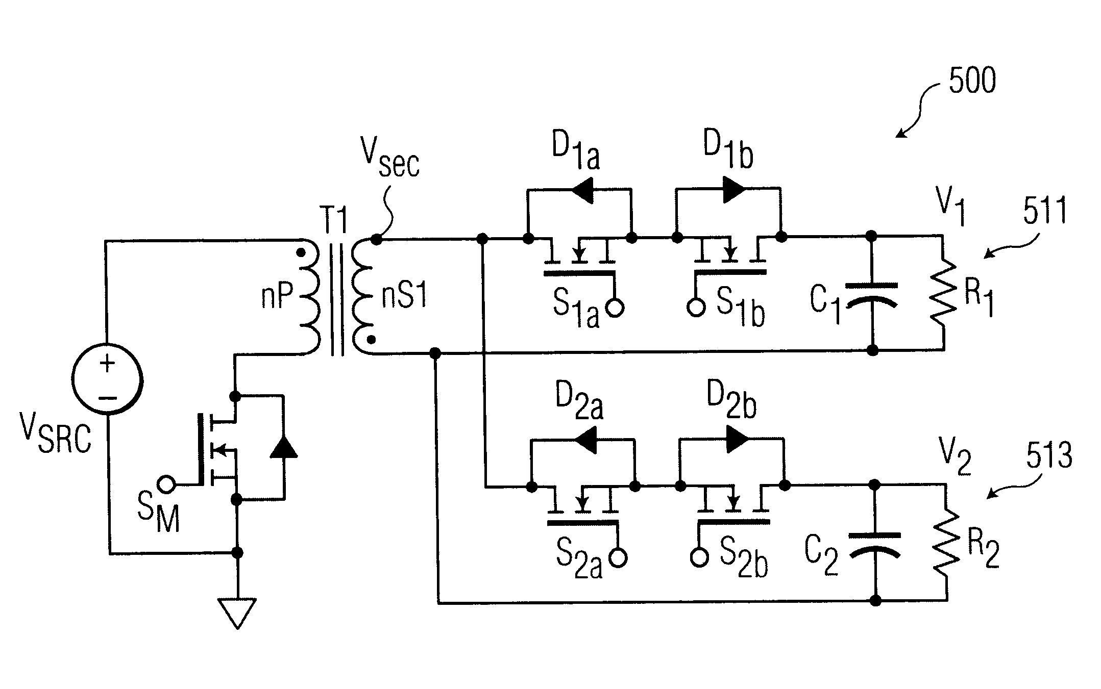
As an example of the ease with which the cycling order can be modified or changed, the present example illustrates what is required to reverse the cycling order of the previous example. Namely, cycling output circuit 513 first followed by output circuit 511. This is achieved as follows.

Prior art output circuit 411 is emulated by output circuit 513 by maintaining switch S.sub.2b of output circuit 513 to be permanently `off`. Prior art output circuit 413 is emulated by output circuit 511 by maintaining switch S.sub.1a of output circuit 511 to be permanently `on`.

SOFT-SWITCHING

Another feature of the present invention is that simultaneous soft-switching of the primary and secondary side switches is maintained.

The secondary switches illustrated in FIG. 5 are preferably implemented as NMOS switches. These switches have two conduction paths, one is the main channel, which is controlled by the gate voltage. When the gate voltage is `on` (i.e., 12V or so with respect to the source) the chann...

second embodiment

FIG. 8 is a schematic diagram of a second illustrative embodiment of a soft-switching flyback converter circuit 800 of the present invention. The present embodiment illustrates a circuit which illustrates how the inventive circuit 800 can be combined with a portion (i.e., one output) of a conventional circuit of the prior art (i.e., FIG. 4). In particular, the inventive circuit 800 is shown to include output circuits 811 and 813. Output circuit 805 illustrates an output circuit in accordance with the prior art. Output circuit 805 illustrates a standard output circuit configuration including a single conventional switch S.sub.3.

As previously described with reference to FIG. 4, prior art output circuit 805, by virtue of its conventional configuration, must be the last output to be sequenced or cycled in the cycling order. By contrast, those output circuits associated with the inventive circuit 800 (i.e., 811, 813) can be sequenced or cycled in any order in accordance with the principl...


PUM


Abstract

A soft-switching multiple output fly-back converter provides output cyclying sequence control. Each of the multiple output circuits includes a bi-directional switching circuit which provides for flexible reconfiguration of the output cycling sequence. Further, the novel circuit allows each of the individual outputs, or any combination thereof, to be independently turned "off' (i.e., removed from the cycling sequence) and re-introduced (i.e., turned "on' again) at a later time as needed.

Description

1. Field of the InventionThe present invention is directed, in general, to the field of DC-to-DC converters. More particularly, the present invention relates to a multiple-output flyback converter having an improved energy cycle sequencing capability.2. Description of The Related ArtConventional flyback switching power supplies commonly include a pair of transformers (actually a pair of coupled inductors) and one or more power switches for alternately coupling an unregulated DC or rectified AC voltage across a primary winding of the power transformer in a series of voltage pulses. These pulses are converted into a series of voltage pulses across one or more secondary windings of the power transformer and then rectified and filtered to provide one or more output DC voltages. The output voltage or voltages of the power converter are commonly regulated by controlling the relative amount of time that the power switch is `on` (i.e., the duty cycle).One common type of switching power supp...

Claims


Application Information

Patent Timeline
Patent Type & Authority Patents(United States)
IPC IPC(8): H02M3/24H02M3/335H02M3/28
CPCH02M3/33561H02M3/28H02M3/335
Inventor BOURDILLON, LAURENCE
Owner KONINKLIJKE PHILIPS ELECTRONICS NV
Why Eureka
Try Eureka