
Hybrid multi-stage circuit

a multi-stage circuit and hybrid technology, applied in the field of hybrid multi-stage circuits, can solve the problems of inherently high dc offset and low frequency (1/f) noise of the amplifier at the input, worse effects, and low achievable amplifier gain in such process technology

Inactive Publication Date: 2003-08-19
QUALCOMM INC
View PDF7 Cites 31 Cited by
  • Summary
  • Abstract
  • Description
  • Claims
  • Application Information

AI Technical Summary

Problems solved by technology

When implemented in an integrated circuit, an amplifier inherently exhibits some amount of DC offset and low frequency (1 / f) noise at its input.
These effects are worse when a low-voltage CMOS process is used to fabricate the amplifier.
Also, the achievable amplifier gain is typically low in such process technology, relative to other linear-IC processes such as bipolar.
The input DC offset, low frequency noise, and low gain of an amplifier can contribute to degrade the performance of an active circuit that employ such amplifier.
For a filter or ADC, such performance degradation may correspond to a reduced dynamic range, which may translate into worse overall performance for the system that employs the filter or ADC.
Multi-sampling switched capacitor circuits, while having lower power consumption and other advantages, are vulnerable to input DC offset and low frequency noise.
Moreover, multi-sampling circuits are typically implemented with n signal paths, and these n-path circuits are sensitive to path mismatch which causes image error.

Method used


Image

  • Hybrid multi-stage circuit
  • Hybrid multi-stage circuit
  • Hybrid multi-stage circuit

Examples


Embodiment Construction

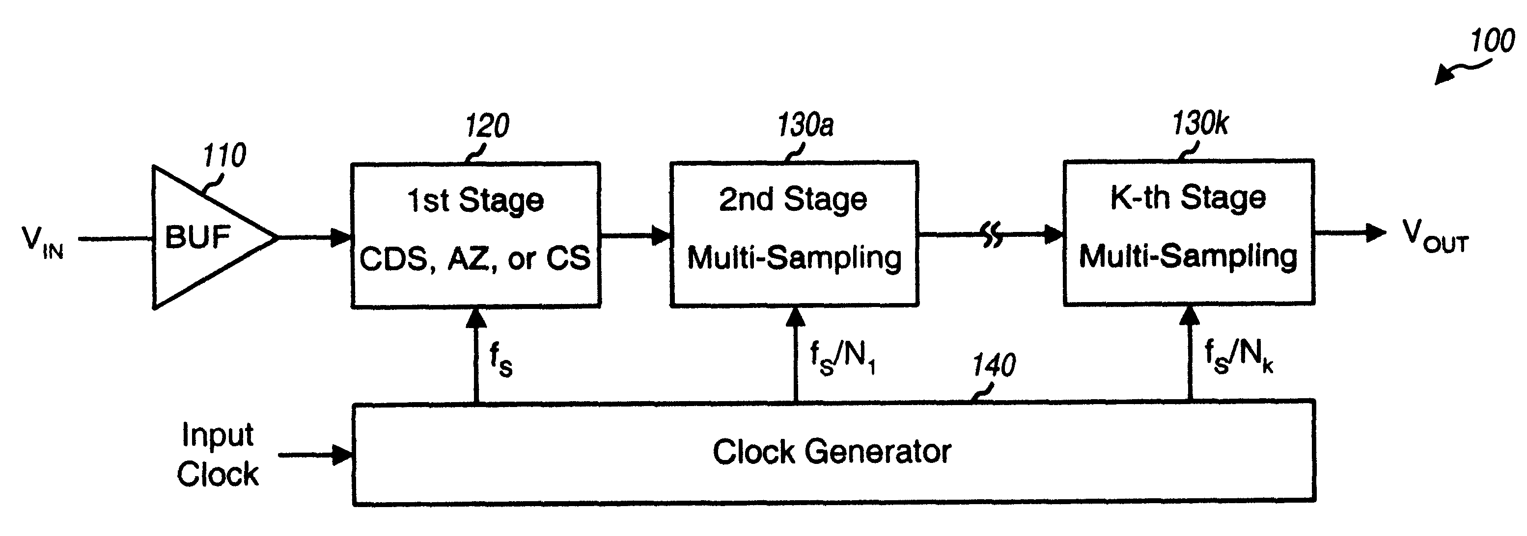
FIG. 1 is a block diagram of a "hybrid" multi-stage circuit 100 utilizing different types of sampling circuit, in accordance with an aspect of the invention. Multi-stage circuit 100 includes an input buffer 110 coupled in series with a number of sampling circuit stages. Buffer 110 provides buffering and may further be designed to provide lowpass filtering of an input signal, V.sub.IN. The buffered signal is then provided to a first stage 120 that processes (e.g., filters) the signal based on a particular transfer function. In an embodiment, first stage 120 is implemented as a single-sampling circuit such as, for example, a correlated double-sampling (CDS) circuit, an auto-zeroing (AZ) circuit, a chopper stabilization (CS) circuit, or some other type of circuit capable of providing similar desired characteristics, which are described in further detail below. By implementing the first stage with a single-sampling circuit, deleterious effects due to input DC offset, low frequency noise...


PUM


Abstract

A multi-stage circuit that includes a number of stages, with at least one stage being of a first type and at least one stage being of a second type. Each stage receives either a circuit input signal or an output signal from a preceding stage, processes (e.g., filters) the received signal, and provides a respective output signal. Each first type (or second type) stage operates based on one or more clock signals having a frequency of fS (or fS / N), where fS is the sampling frequency and N is an integer greater than one. Each first type stage may be implemented with a correlated double-sampling circuit, an auto-zeroing circuit, or a chopper stabilization circuit. Each second type stage may be implemented with a multi-sampling (i.e., double-sampling or higher order sampling) circuit. The multi-stage circuit may be designed to implement a lowpass filter, a DELTASIGMA ADC, or some other circuit.

Description

I. Field of the InventionThe present invention relates to circuits. More particularly, the present invention relates to a hybrid multi-sampling circuit utilizing different types of sampling circuit.II. Description of the Related ArtMany communication and data transmission systems employ active filters, analog-to-digital converters (ADCs), and other active circuits to perform some of the required signal processing. These active circuits may utilize operational amplifiers (op-amps) as one of the basic building elements. The amplifiers can be designed to provide high input impedance and large signal gain.When implemented in an integrated circuit, an amplifier inherently exhibits some amount of DC offset and low frequency (1 / f) noise at its input. These effects are worse when a low-voltage CMOS process is used to fabricate the amplifier. Also, the achievable amplifier gain is typically low in such process technology, relative to other linear-IC processes such as bipolar.The input DC off...

Claims


Application Information

Patent Timeline
Patent Type & Authority Patents(United States)
IPC IPC(8): H03M3/02
CPCH03M3/496H03M3/34H03M3/342H03M3/384H03M3/02
Inventor BAZARJANI, SEYFOLLAH
Owner QUALCOMM INC
Learn More