Glare shielding device of welding helmet and method of controlling the same

a welding helmet and shielding device technology, applied in the field of welding helmet shielding device, can solve the problems of troublesome task, high power consumption, time delay,

Inactive Publication Date: 2003-09-02
OTOS TECH
View PDF9 Cites 78 Cited by
  • Summary
  • Abstract
  • Description
  • Claims
  • Application Information

AI Technical Summary

Problems solved by technology

Firstly, a time delay occurs between an input of welding light and an operation of the antiglare device.
Secondly, power consumption is high due to an operation of a control circuit having a microcomputer for continuously detecting a variation of an input welding light.
This is a troublesome task.
Fifthly, in case that a welding signal is detected using only a light signal, since detected signals depend on a welding method and a welding machine, the glare shielding device may abnormally operate.
In this case, since a continuous light shielding phenomenon may occur due to a non-intended abnormal operation that may be generated by a latent magnetic filed in surroundings, workers can not discriminate welding light due to the continuous light shielding phenomenon, whereupon workers can not check a welding state.

Method used


Image

  • Glare shielding device of welding helmet and method of controlling the same
  • Glare shielding device of welding helmet and method of controlling the same
  • Glare shielding device of welding helmet and method of controlling the same

Examples


Embodiment Construction

Reference will now be made in detail to a preferred embodiment of the present invention, example of which is illustrated in the accompanying drawings.

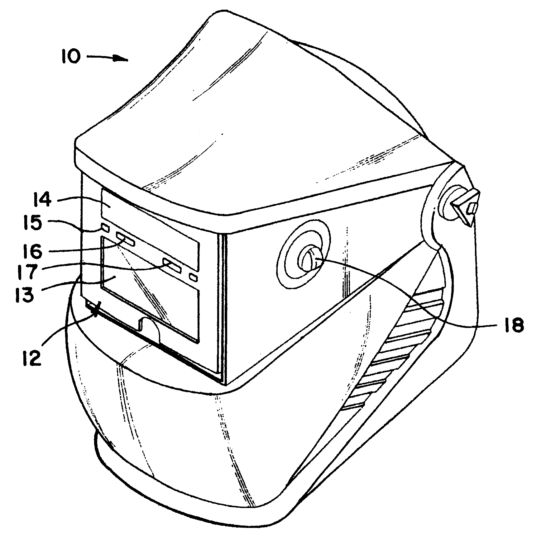
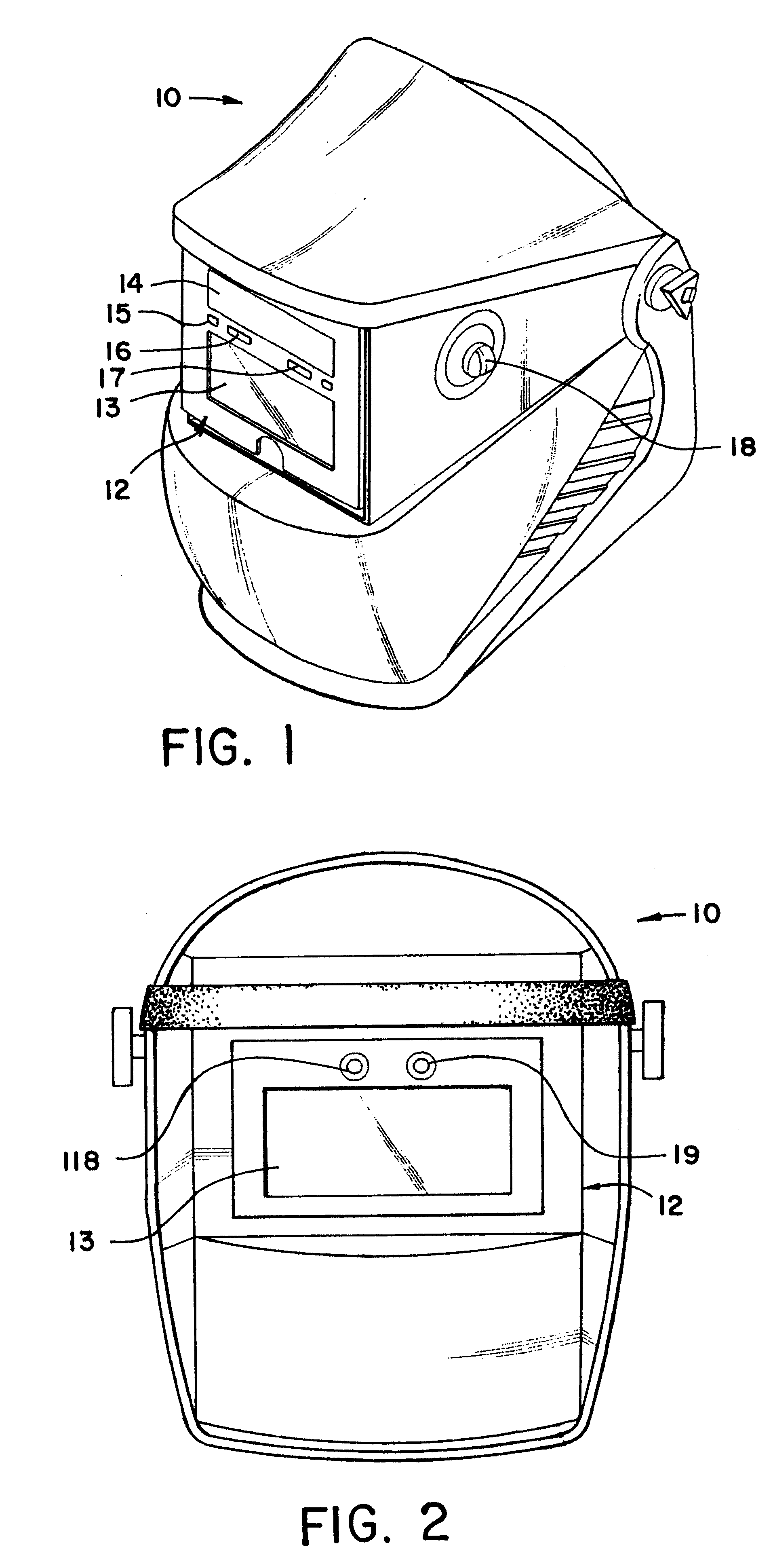
FIG. 1 is a perspective view illustrating a welding helmet according to the preferred embodiment of the present invention. As shown in FIG. 1, the welding helmet includes a glare shielding plate 12 arranged on a front surface thereof. The glare shielding plate 12 is made of a noncombustible plastic material that is a relatively light-weight material. The glare shielding plate 12 includes a liquid crystal panel 13, a solar battery 14, a photosensor 15, an antenna 16, and a temperature sensor 17. The welding helmet 10 further includes a first adjusting knob 18 arranged on its side surface. The first adjusting knob 18 serves to adjust a level of a driving voltage of a liquid crystal. A light filter is attached on a surface of the liquid crystal panel 13, so that only the visible ray can be transmitted.

FIG. 2 is a back view illustrating th...


PUM

PropertyMeasurementUnit
temperatureaaaaaaaaaa
off time t3aaaaaaaaaa
electrical energyaaaaaaaaaa

Abstract

The present invention discloses a glare shielding device. The glare shielding device includes a microprocessor for controlling an activation time and a driving time of a liquid crystal panel. The microprocessor generates an activation control signal of a liquid crystal activating portion, a driving control signal of a liquid crystal driving portion, and a power off control signal in response to a simultaneous detection of a welding light and a high frequency generated during a welding process. The liquid crystal activating portion becomes a floating state in a standby mode and activates the liquid crystal panel using a minus voltage between a high voltage and an activation voltage. The liquid crystal driving portion becomes a floating state in a standby mode and drives the liquid crystal panel in response to the driving control signal.

Description

CROSS REFERENCEThis application claims the benefit of Korean Patent Application No. 1999-52109, filed on Nov. 23, 1999, and the benefit of Korean Patent Application NO. 2000-59958, field on Oct. 12, 2000, under 35 U.S.C. .sctn.119, the entirety of which is hereby incorporated by reference.1. Field of the inventionThe present invention relates to a glare shielding device of a welding helmet and a method of controlling the same.2. Description of Related ArtIn recent, glare shielding devices are widely used in the welding and cutting torch technology in order to protect eyes of workers. With such glare shielding devices the radiation above 780 nm (infrared) and below 365 nm (ultraviolet) are filtered and only the radiation in the visible range is dimmed, so that workers can discriminate a welding position of a specific spot.U.S. Pat. No. 5,315,099 (German Patent No. 2,606,416) discloses a glare shielding device which includes an electro-optical glare shield having at least one liquid c...

Claims


Application Information

Patent Timeline
Patent Type & Authority Patents(United States)
IPC IPC(8): A61F9/04A61F9/06
CPCA61F9/065
Inventor BAE, YOUNG-DAWN
Owner OTOS TECH
Why Eureka
Try Eureka