

GIS post insulator with an integrated barrier
a post insulator and integrated technology, applied in the direction of insulated conductors, power cables, cables, etc., can solve the problems of surface discharges which originate on the post insulator, or move to it, cannot be stopped, and the risk of dielectric flashovers resulting from surface discharges in the area of post insulators is still very high, so as to reduce the e-field load and reduce the effect of e-field loads
- Summary
- Abstract
- Description
- Claims
- Application Information
AI Technical Summary
Benefits of technology
Problems solved by technology
Method used
Image

Examples
Embodiment Construction
The object of the present invention is to specify a post insulator for a gas-insulated switchgear assembly, a gas-insulated switchgear assembly, and a switchgear assembly module with a post insulator, which have an improved breakdown strength. According to the invention, this object is achieved by the features of the independent claims.
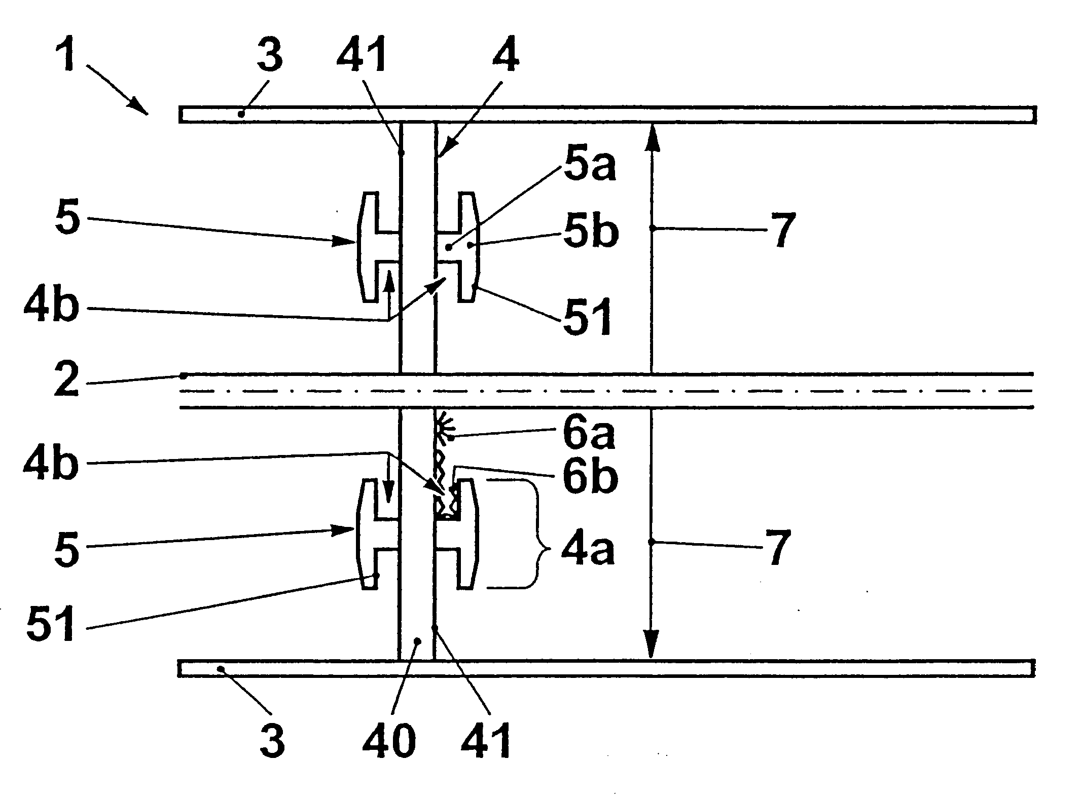
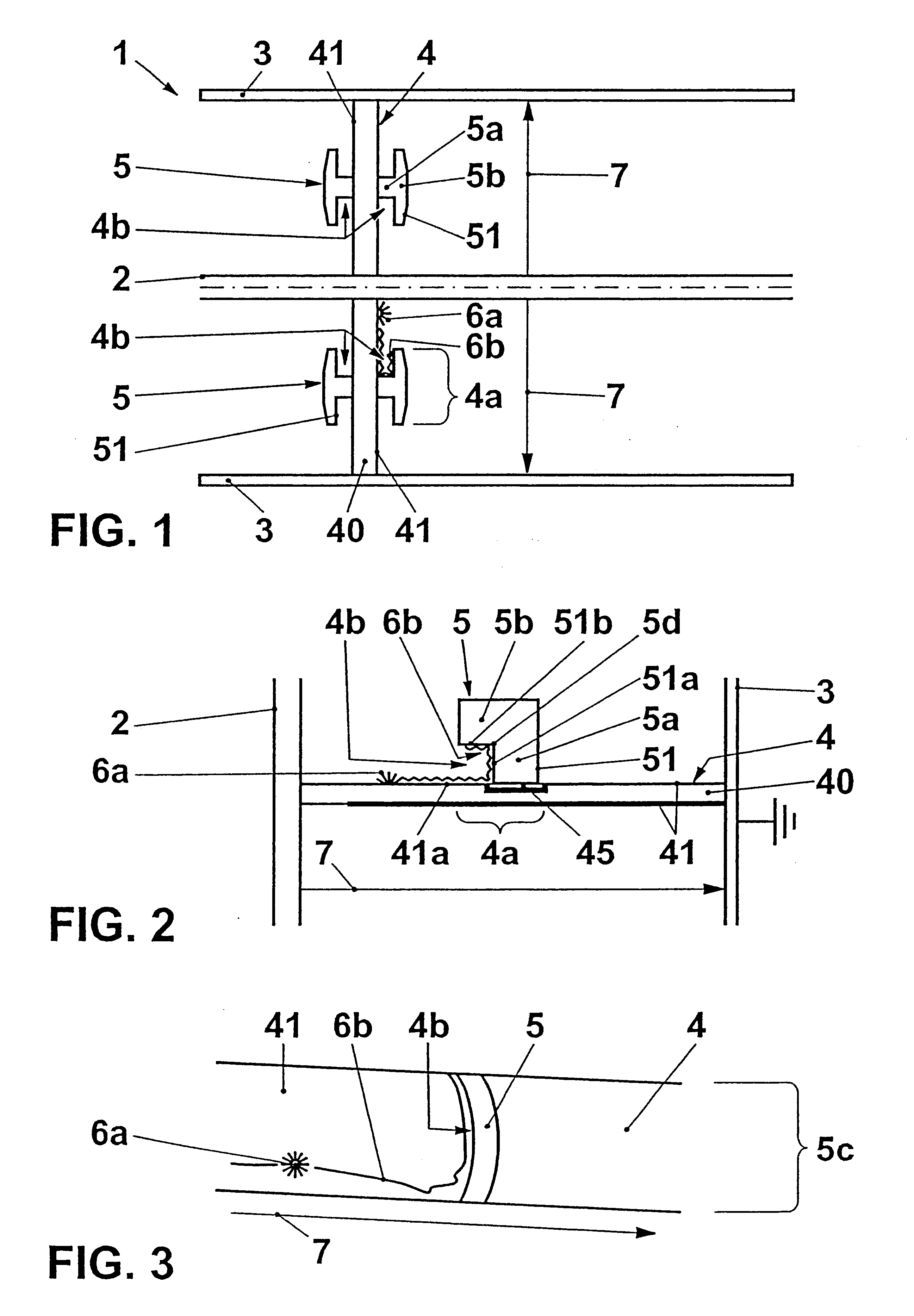
In a first aspect, the invention comprises a post insulator with a base body for supporting a high voltage component on a holder, with the post insulator being designed to bridge a high voltage potential difference between the component and the holder and having a surface, which extends essentially along a bridging direction, i.e. essentially along a potential gradient in the undisturbed operating state, of the base body, the surface of the post insulator having a cup-shaped indentation, which is concave and open toward the component or the holder, in an area between the component and the holder. The concave cup shape is used to divert surface dischar...
PUM
| Property | Measurement | Unit |
|---|---|---|
| angle | aaaaa | aaaaa |
| voltage | aaaaa | aaaaa |
| angle | aaaaa | aaaaa |
Abstract
Description
Claims
Application Information