
System LSI development apparatus and the method thereof for developing a system optimal to an application

a technology of system lsi and development apparatus, which is applied in the direction of cad circuit design, program control, instruments, etc., can solve the problems of inability to fully achieve application performance, difficulty in developing an lsi with its more optimal performance, and inability to handle configuration including user defined hardware modules to be added to the processor

Inactive Publication Date: 2003-10-14
KK TOSHIBA
View PDF7 Cites 57 Cited by
  • Summary
  • Abstract
  • Description
  • Claims
  • Application Information

AI Technical Summary

Benefits of technology

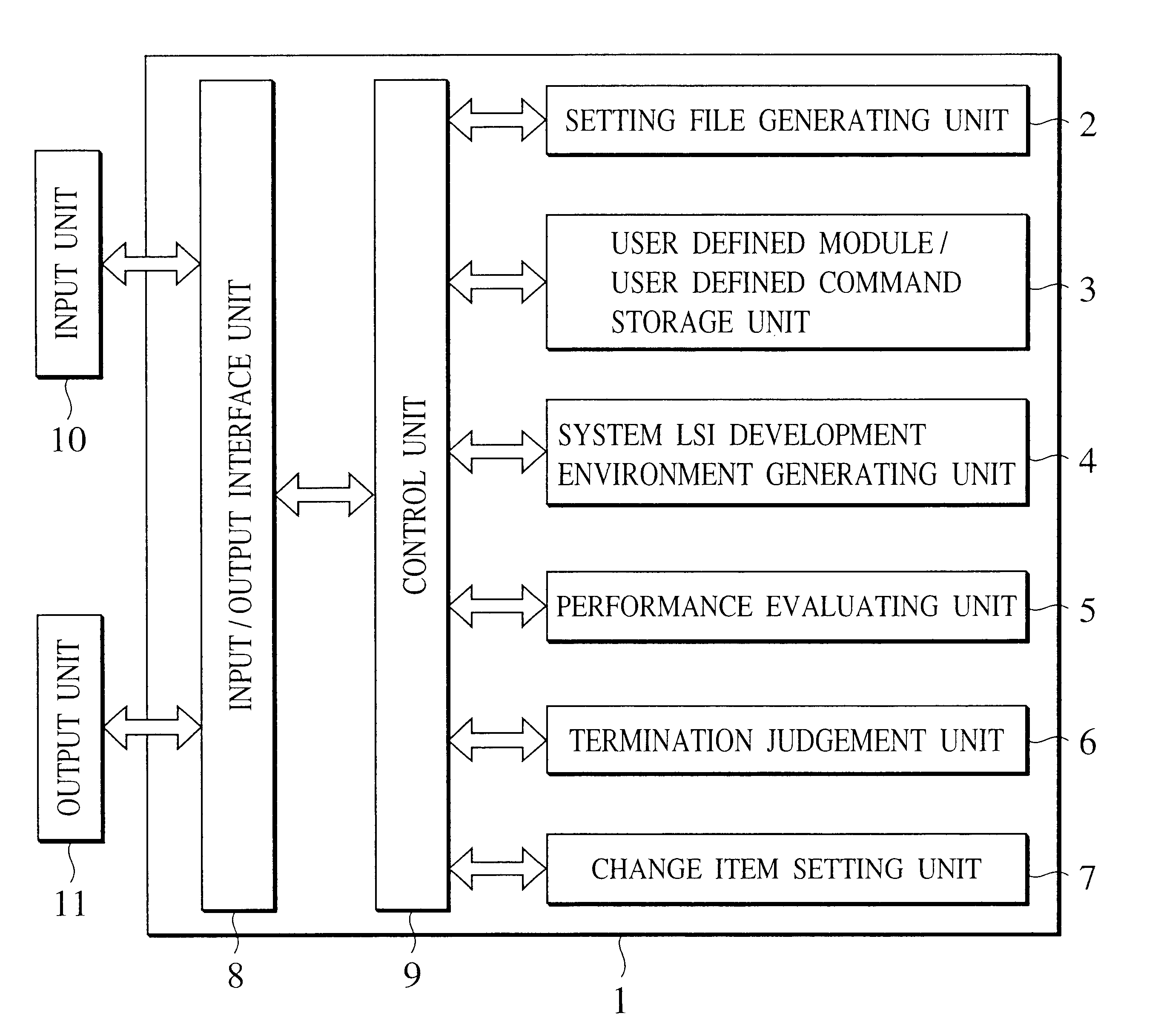
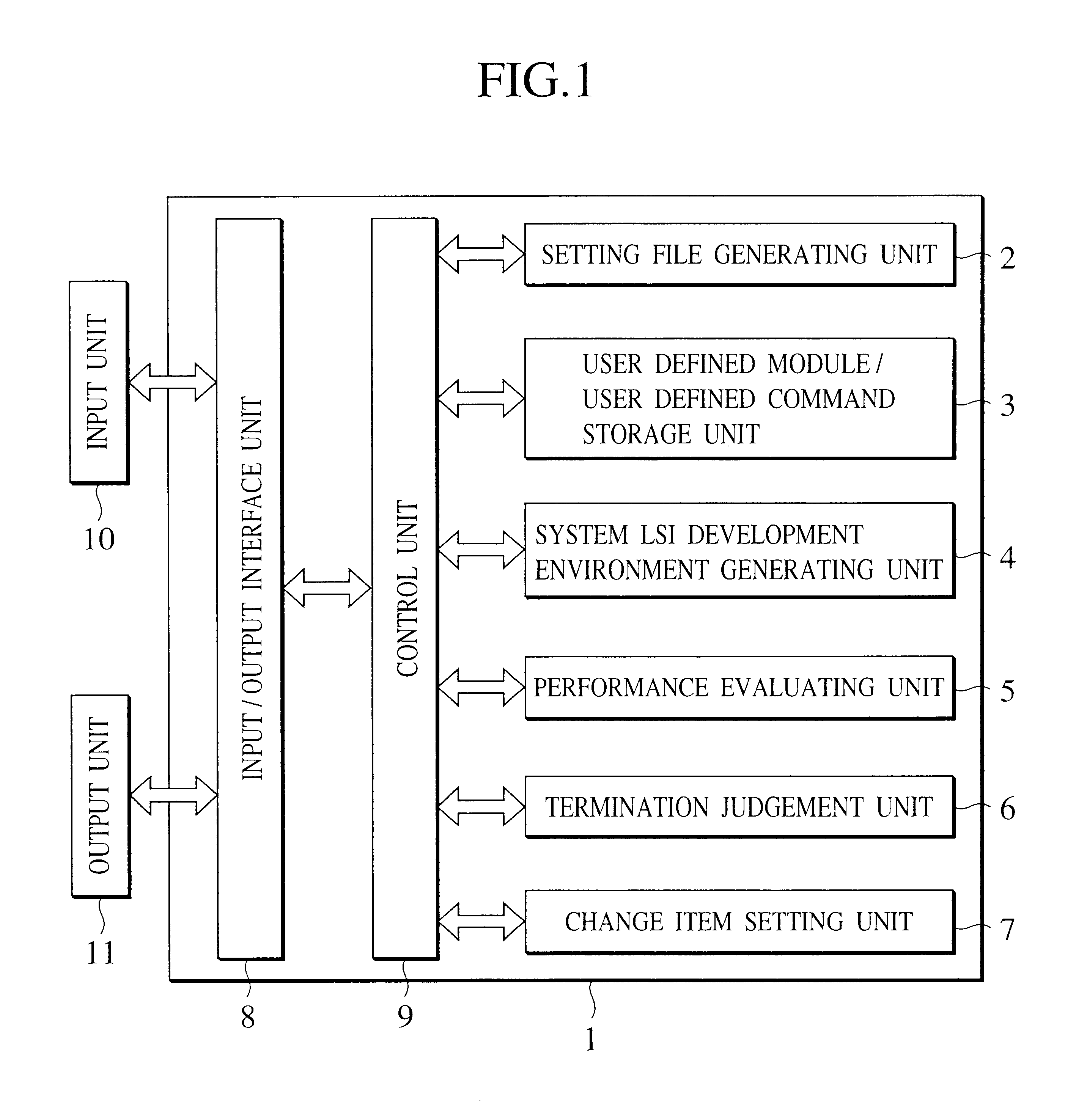
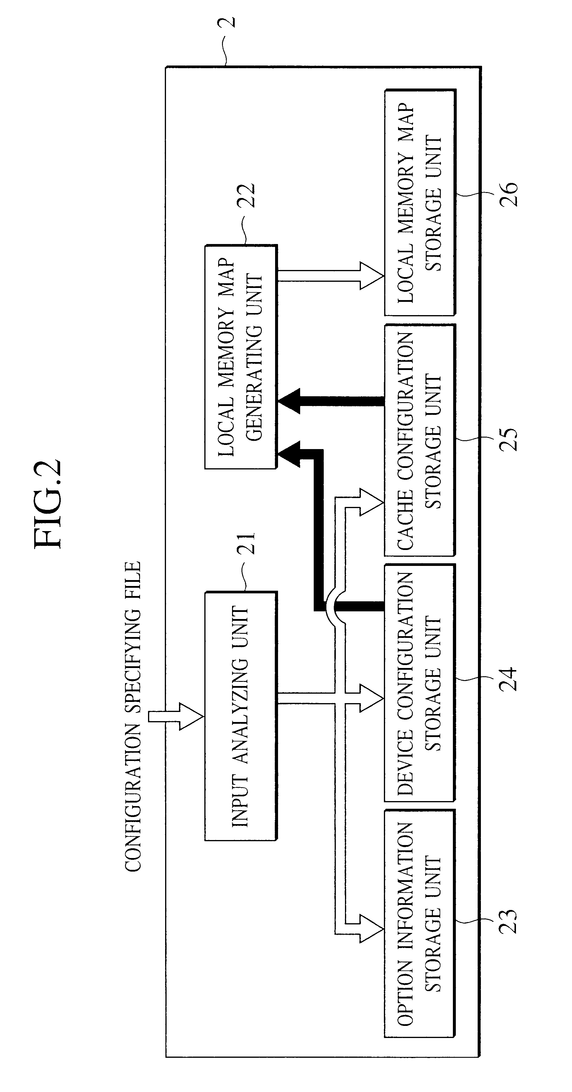
According to the present invention, there is provided a system LSI development apparatus comprising a plurality of software components that operate on a computer system, used for developing and designing a system LSI that contains a processor having at least an optional instruction defined therein, the system LSI development apparatus comprising: a system LSI development environment generating unit causing software to operate based on change item definition information concerning system LSI development and design, thereby generating hardware description, verification environment, and development and design tools for the system LSI, wherein the change item definition information contains at least one item of information concerning an optional instruction information, a user defined module and a multiprocessor configuration. According to the thus configured system LSI development apparatus, with respect to all possible combinations of change item definition information containing at least one of the optional instruction, user defined module and multiprocessor configuration, system LSI hardware containing a processor having at least an optional instruction defined therein, a plurality of verification environment and a development tool suite are consistently created in an exhaustive or parallel manner, thus making it possible to develop a system LSI optimal to applications within a short period of time.

Problems solved by technology

In general, in the case where a general-purpose processor is incorporated in an LSI, the hardware design cost is almost equal to zero; however, the performance of applications cannot be fully achieved.
However, in prior art, only processor configuration can be customized, and a configuration including user defined hardware modules to be added to the processor cannot be handled.
Thus, currently, as for an LSI configuration including processor and dedicated hardware configuration (description), architecture consideration, performance evaluation, design verification and software development cannot be performed, thus making it difficult to develop an LSI with its more optimal performance.
If a memory area having no corresponding physical memory mounted on a working substrate is accessed, a bus error occurs, and the subsequent operation is not guaranteed.
Further, in the case where the simulator operates in communication with the debugger, it cancels a simulation operation, and waits for debugger instruction entry, outputs an error indicating access to an invalid region, and conveys a program error to a user earlier and certainly.
However, in the case of a write access, the contents of an address are unintentionally rewritten, and the subsequent execution result may become unexpected.
Even in the case where this incorrect program is executed by the RTL simulator, such error cannot be found immediately.
However, the development time tends to increase since an operator has to stand by.
However, the target performance cannot be achieved in this situation, and thus, a DSP for performing computation is added as a user defined module.
In recent years, restoration processing of compressed data or data display processing and the like is likely to be substituted by software from the aspect of cost or speed, and software processing rate increases, and is complicated.
In the case where these processes are performed by one processor, plurality of processing functions plus coprocessor or user defined module control must be performed, and the target performance cannot be obtained.
Thus, the user can know whether or not LSI performance is insufficient, resulting in speedy configuration item change and reduced system LSI performance period.

Method used


Image

  • System LSI development apparatus and the method thereof for developing a system optimal to an application
  • System LSI development apparatus and the method thereof for developing a system optimal to an application
  • System LSI development apparatus and the method thereof for developing a system optimal to an application

Examples


Embodiment Construction

A system LSI development apparatus according to other embodiments of the present invention comprises a so called general-purpose machine, a workstation, a PC (Personal Computer), and an NC (Network Computer) or the like. This system has its appearance shown in FIG. 19, for example, and comprises a floppy disk drive 52 and an optical disk drive 54. Then, a floppy disk 53 is inserted into a floppy disk drive 52; an optical disk 55 is inserted into an optical disk drive 54; and predetermined readout operation is performed, whereby programs stored in these recording media can be installed in a computer system. In addition, a predetermined drive device 57 is connected, whereby installation or data reading and writing can be executed by using a ROM 58 that serves as a memory device or a cartridge 59 that serves as a magnetic tape.

In addition, the system LSI development apparatus according to the embodiments of the present invention may be programmed and stored in a computer readable recor...


PUM


Abstract

In this disclosure, based on change item definition information concerning system LSI development and design, software used for development and design of a system LSI that contains a processor having optional instructions defined therein is operated, and system LSI hardware description, verification environment and a development and design tools are generated, thus making it possible to develop a system LSI optimal to an application within a short period.< / PTEXT>

Description

The subject application is related to subject matter disclosed in the Japanese Patent Applications No.Tokugan2000-027432 filed in Feb. 2, 2001, to which the subject application claims priority under the Paris Convention and which is incorporated by reference herein.1. Field of the InventionThe present invention relates to a system LSI development apparatus comprising a plurality of software components that operate on a computer system, used for developing and designing a system LSI that contains a configurable processor having at least an optional instruction defined therein; and the system LSI development method thereof.2. Description of the Related ArtIn recent years, an LSI design and development system for developing an LSI optimal to applications within a short period of time is expected because of diversified needs for an LSI oriented to an embedded device such as multimedia processing and its shorter market cycle.In general, in the case where a general-purpose processor is in...

Claims


Application Information

Patent Timeline
Patent Type & Authority Patents(United States)
IPC IPC(8): G06F17/50G06F11/22G06F11/26
CPCG06F17/5045G06F17/5022G06F30/30G06F30/33G06F30/3308
Inventor MATSUI, NOBUOMIZUNO, ATSUSHIOHYAMA, RYUICHIROTANGODA, MEGUMIUCHIDA, KATSUYA
Owner KK TOSHIBA
Learn More