Shape memory tubular stent

a memory tubular and stent technology, applied in the field of stent shape memory tubular stent, can solve the problems of inability to work, inability to clot, and placement of fibers or wires within the aneurysm to induce clotting, so as to prevent further enlargement and rupture, and reduce trauma

Inactive Publication Date: 2003-10-21
UNSWORTH JOHN DUNCAN +1
View PDF12 Cites 286 Cited by
  • Summary
  • Abstract
  • Description
  • Claims
  • Application Information

AI Technical Summary

Benefits of technology

Any number of tubes can be arranged with their longitudinal axes parallel and their sides connected to each other at various places to form the walls of a larger tube. This larger tube can the be radially expanded by causing the smaller tubes to bend between the points of connection forming a webbed tubular structure. If the tubes are made of shape memory alloy (SMA) the larger webbed tube can be heat treated to its shape set temperature and when subsequently cooled below the martensitic finish temperature it can be radially formed into a more compact structure. After the shape setting and deformation steps, the expanded tubular structure can be recovered by heating it above the austenitic finish temperature. In its compact martensitic form, the webbed tube can be inserted into the lumen of a tubular body, then heated to support the walls forming the lumen.
It can be readily be seen that the stent fabricated from tubes as described, whether in one piece or a train of sections, offers the advantage of being able to vary the final shape of the stent by varying the parts of the webbed structure that are recovered. In the case of a train of sections, each can be deployed sequentially and separations between them can be controlled, either in advance, by their placement on the distal end of the catheter, or on the fly, by withdrawing the delivery catheter a desired distance, between deployments of the sections.
The fact that a balloon need not be used for deployment, although some preferred embodiments may include such a balloon, has the advantage of not impeding or stopping blood flow through the lumen into which it is placed, and deployed. While an important feature for stenting occlusions, it is especially important for aneurysms of the brain, where the inference with blood flow, for even a short time, can lead to serious brain damage. The controlled deployment of the stent and sealing means, also reduces trauma to the vessels into which the stent is deployed.
The method herein described allows for the stent to be covered with a membrane, which may be biodegradable, or other features that allow the stent to be impervious, or approximately impervious to blood or fluid flows through any openings in the walls of the stent. This features allows an aneurysm to be blocked off from the normal flow of blood or fluids, which travels through the lumen of the stent. By thus blocking off the aneurysm, clotting occurs in the aneurysm which causes it to form a plug that prevents further enlargement and rupture. A further advantage of stenting the vessel at and adjacent to the aneurysm, is that the aneurysm can be of any shape. Other methods, such as the placement of fibers or wires within the aneurysm to induce clotting, do not work if the opening in the vessel lumen is too large in relation to the size of the aneurysm bulb.

Problems solved by technology

While an important feature for stenting occlusions, it is especially important for aneurysms of the brain, where the inference with blood flow, for even a short time, can lead to serious brain damage.
Other methods, such as the placement of fibers or wires within the aneurysm to induce clotting, do not work if the opening in the vessel lumen is too large in relation to the size of the aneurysm bulb.

Method used


Image

  • Shape memory tubular stent
  • Shape memory tubular stent
  • Shape memory tubular stent

Examples


Embodiment Construction

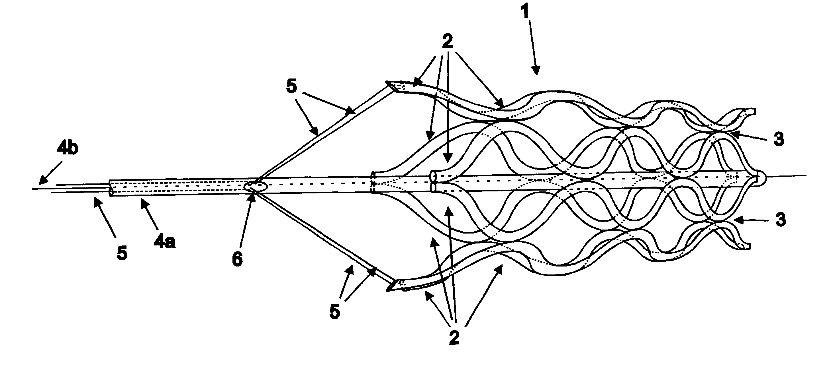
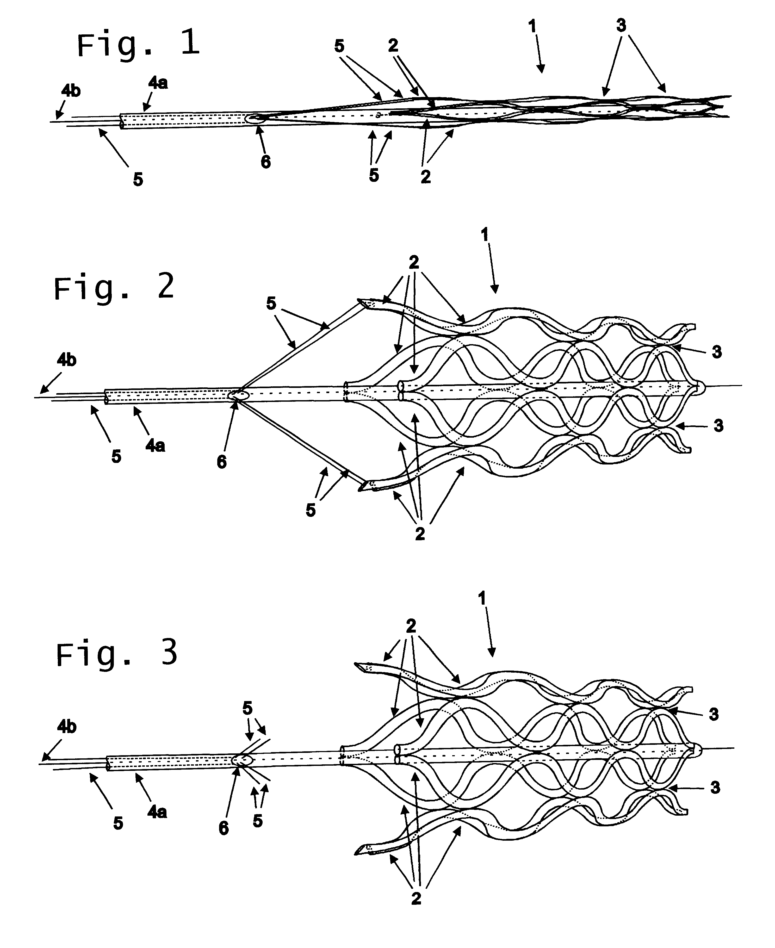
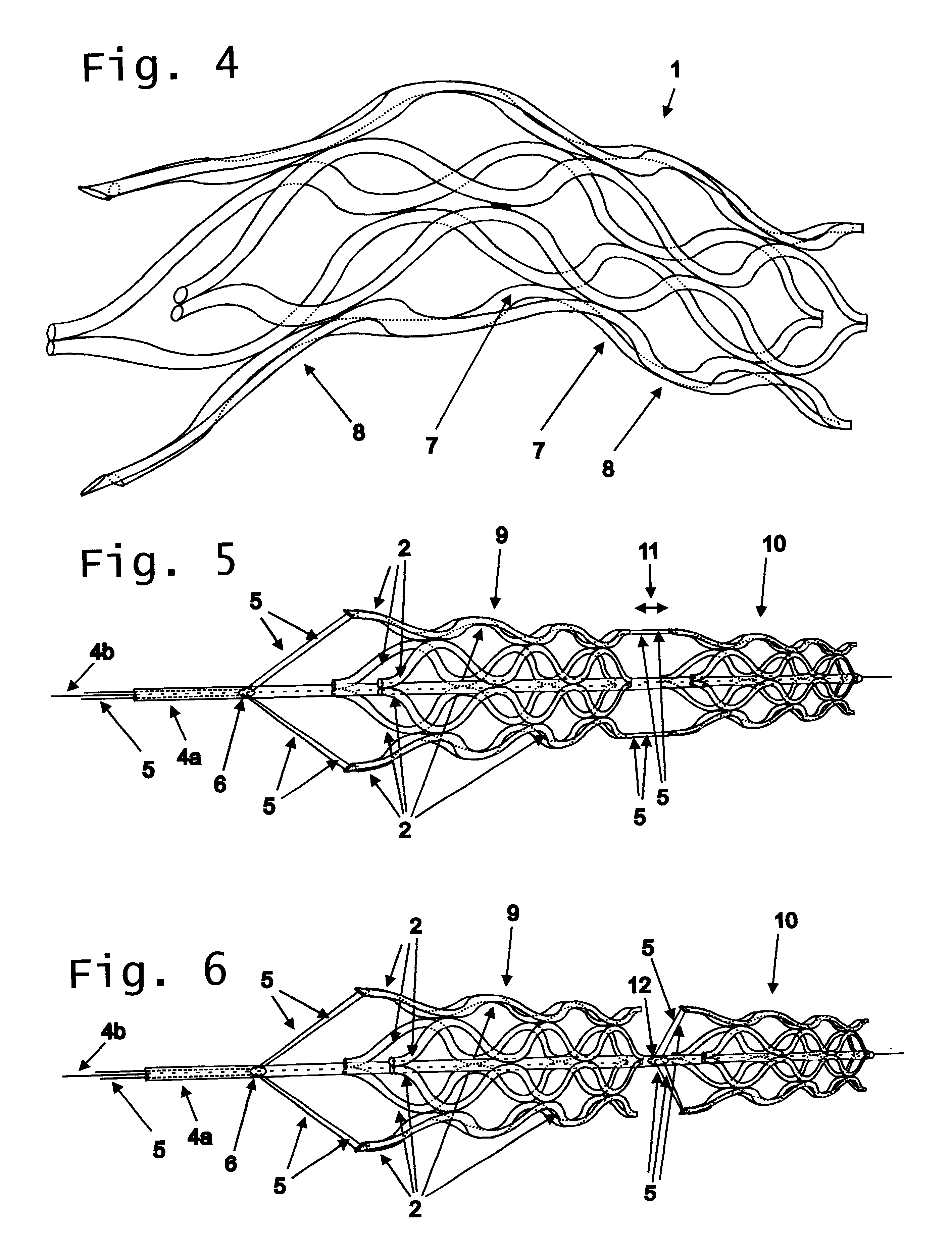
In its radially contracted state for introduction into the body lumen to be dilated or supported, the stent 1 is a webbed tubular structure or an outer contour as shown in FIG. 1. The eight tubes 2 are connected at nodal points 3 by welds or other connecting means. The stent is delivered into the body lumen at approximately the distal end of a delivery catheter 4 to which it is detachably attached. Although the preferred embodiment of the invention shown in FIG. 1 is comprised of eight tubes, any number of tubes could comprise the webbed tubular structure.

In the radially expanded shape as shown on FIG. 2 the tubes 2 have had their shapes recovered by the application of photo-thermal energy delivered by optical fibers 5.from a photo-thermal source coupled to the proximal end of the said optical fiber. The optical fibers that deliver the photo-thermal energy that initiate the shape recovery pass through the delivery catheter and exit it at orifices 6 of the said delivery catheter and ...


PUM


Abstract

A stent radially expandable from a radially contracted introduction state into a radially expanded position state, in which the final shape of the stent can be controlled by varying the amount and places energy is delivered onto the interior surfaces of the tubes from which the stent is fabricated, and means to seal the opening into the aneurysm, thereby causing the blood therein to clot and preventing the aneurysm from growing or rupturing.

Description

This in invention relates to a stent for dilating and keeping open vessels and sealing-off aneurysms and inducing clotting in aneurysms, with a radially contracted stent for introduction into the vessel and with a radially expanded stent after introduction into the vessel.BACKGROUND AND SUMMARY OF INVENTIONSuch stents or implantable catheters to be introduced into a body cavity, a vessel or the like can be made from plastic or an inert metal, such as steel or nickel-titanium alloys. Such stents are also referred to as endovascular or endoluminal stents or endoprostheses. For example, when dilating the ureter, the stents are used in the prostate region. In the case of benign prostate hyperplasia (BPH) or also in sclerotic blood vessels for dilating and keeping open the same. The stents have material areas and gaps between them. Thus, it is possible for the wall tissue of the organ kept open to grow round the stent. Stents can have a spiral construction, can be in the form of a helica...

Claims


Application Information

Patent Timeline
Patent Type & Authority Patents(United States)
IPC IPC(8): A61F2/06A61F2/00A61F2/90
CPCA61F2/90A61F2/954A61F2/856A61F2210/0047A61F2002/065A61F2002/9505
Inventor UNSWORTH, JOHN DUNCANWARAM, THOMAS COLE
Owner UNSWORTH JOHN DUNCAN
Why Eureka
Try Eureka